ELECTRICAL TECHNOLOGY: POWER SYSTEMS GRADE 12 QUESTIONS - 2018 SEPTEMBER PREPARATORY EXAM PAPERS AND MEMOS
Share via Whatsapp Join our WhatsApp Group Join our Telegram GroupELECTRICAL TECHNOLOGY: POWER SYSTEMS
GRADE 12
NATIONAL SENIOR CERTIFICATE
SEPTEMBER 2018
INSTRUCTIONS AND INFORMATION
- This question paper consists of FIVE questions.
- Sketches and diagrams must be large, neat and fully labelled.
- Show ALL calculations and round off answers correctly to TWO decimal places. Show the units for ALL answers of calculations.
- Number the answers correctly according to the numbering system used in this question paper.
- You may use a non-programmable calculator.
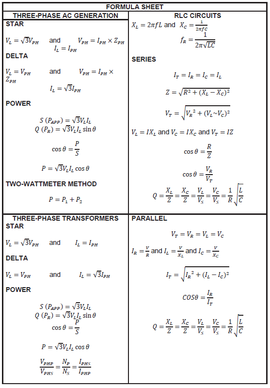
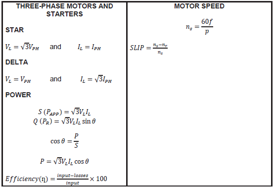
- A formula sheet is provided at the end of this question paper.
- Write neatly and legible.
QUESTION 1: OCCUPATIONAL HEALTH AND SAFETY
1.1 Summarise the purpose of the Occupational Health and Safety Act. (2)
1.2 Explain the ‘let-go’ current during an electrical shock.(2)
1.3 State ONE unsafe condition that must be avoided in a workshop. (1)
1.4 Give ONE unsafe act in a school workshop that can cause an accident. (1)
1.5 Describe TWO standard treatments for shock. (2)
[8]
QUESTION 2: RLC
2.1 A series RLC circuit consists of an inductor with an inductive reactance of 24 Ω, a resistor with a resistance of 12 Ω and a capacitor with a capacitive reactance of 18 Ω connected across a 30 V supply.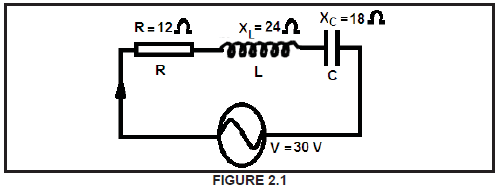
Calculate the:
2.1.1 Impedance of the circuit (3)
2.1.2 Current flowing through the circuit (3)
2.1.3 Voltage across each component in the circuit (6)
2.1.4 Prove by calculation that the sum of the three voltages equals the supply voltage (3)
2.1.5 Circuit phase angle and state whether is it leading or lagging (3)
2.1.6 Draw a fully labelled voltage phasor diagram (5)
2.2 The phasor diagram in FIGURE 2.2 indicates the current values flowing through the components of a parallel circuit connected across a 240 V/50 Hz supply. Refer to the diagram below and answer the questions that follow.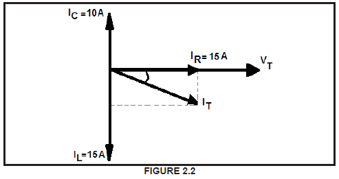
Calculate the:
2.2.1 Total current flow through the circuit (3)
2.2.2 Inductive reactance (3)
2.2.3 Inductance of the coil (3)
2.3 Define the following terms with reference to RLC circuits:
2.3.1 Resonance (2)
2.3.2 Q-factor in a parallel circuit (2)
2.4 A circuit with a resistor of 4 Ω, an inductor with an inductive reactance of 157 Ω and a variable capacitor set to 120 μF are connected in series to a 100 V/50 Hz supply.
Given: R = 4 Ω
XL = 157 Ω
Cvar = 120 μF
Vs = 100 V
f = 50 Hz
Calculate the:
2.4.1 Value of the capacitance that will result in resonance at 50 Hz (3)
2.4.2 Q-factor of the circuit at resonance (3)
[42]
QUESTION 3: THREE-PHASE AC GENERATION
3.1 Draw a labelled waveform diagram of a three-phase system. (4)
3.2 Describe apparent power with reference to AC generation. (3)
3.3 A three-phase star connected load is supplied by a 40 kVA generator at a current of 25 A. The power factor of the load is 0,87 lagging.
Calculate:
3.3.1 The line voltage (3)
3.3.2 The phase voltage (3)
3.3.3 The reactive power (4)
3.4 Explain why the power factor of a load is corrected. (3)
3.5 Three loads, with impedance of 45 Ω each, are connected in star to a 415 V three-phase supply line operating at a power factor of 0, 85 lagging. Calculate:
3.5.1 The current through each load (impedance) (4)
3.5.2 The real power (3)
3.5.3 The apparent power (3)
3.6 Two wattmeters are connected to a balanced three-phase system. Wattmeter R gives a reading of 3 kW and wattmeter B gives a reading of 8, 5 kW.
Calculate the power factor. (3)
3.7 Define real power with reference to AC generation. (1)
[34]
QUESTION 4: THREE-PHASE TRANSFORMERS
4.1 Explain the function of a transformer in a distribution network. (2)
4.2 List THREE requirements that must be satisfied for three single-phase transformers to be connected as a three-phase transformer. (3)
4.3 Describe how an increase of the load will affect the primary current of a transformer. (4)
4.4 Explain the purpose of the oil in a transformer. (4)
4.5 Give THREE types of losses that occur in transformers. (3)
4.6 A delta-star connected transformer supplies a factory with 85 kW of electrical power. The current is lagging the voltage with a phase angle of 36,87o. The total losses in the transformer are 12,5 kW. The primary line voltage is 13,8 kV and the secondary line voltage is 450 V.
Calculate:
4.6.1 The secondary line current (3)
4.6.2 The apparent power (2)
4.6.3 The primary phase current (5)
[26]
QUESTION 5: THREE-PHASE MOTORS AND STARTERS
5.1 State THREE advantages of squirrel cage induction motors when compared to other similar induction motors. (3)
5.2 Give TWO applications of induction motors. (2)
5.3 The stator of a three-phase induction motor driving a conveyor belt has 48 poles and the supply frequency is 50 Hz. Calculate the synchronous speed of the motor. (4)
5.4 Draw TWO sketches of a terminal box of an induction motor and indicate a star connection on one and a delta connection on the other one. (4)
5.5 Explain how the direction of rotation of a three-phase motor can be reversed (2)
5.6 List ANY of the important information shown on the name plate of a motor. (1)
5.7 Describe why it is necessary to use a starter with induction motors. (4)
5.8 In an electrical test to determine the insulation resistance of the windings, the megger was connected to the U2 and W1 terminals. The reading on the megger was 35 Ω. Conclude whether the motor can be activated or not. (3)
5.9 As part of the electrical test, the megger was connected to terminals U1 and E. If the motor is in a good condition, what sort of reading can be expected? (2)
5.10 The rotor speed of a squirrel cage induction motor is 3 384 rpm and the synchronous speed is 3 600 rpm. Calculate the slip. (3)
5.11 The losses of a 25 kW squirrel cage induction motor amounts to 2,2 kW.
Calculate the efficiency. (3)
5.12 The following information appears on the nameplate of a squirrel cage motor:
Current = 20 A
Voltage = 415 V
Power factor = 0, 8
Efficiency = 90 %
Determine the maximum power the motor can deliver. (3)
[34]
QUESTION 6: PROGRAMMABLE LOGIC CONTROLLERS
6.1 Name the industrial control system that the PLC was developed to replace. (1)
6.2 Explain TWO disadvantages of the industrial control system used before PLC’s. (2)
6.3 Give THREE advantages of using a PLC over the older industrial control system. (3)
6.4 Describe THREE of the safety steps to be considered when using programmable controlled equipment. (3)
6.5 Describe the method used to convert an analogue signal into a ‘standardised’ digital form ready for use by a PLC. (4)
6.6 Explain what is meant by Binary Code Decimal (BCD). (3)
6.7 Convert the following decimal numbers into BCD code:
6.7.1 0110 0011 0100 0111 (2)
6.7.2 1001 0010 0100 1000 (2)
6.8 Explain why an opto-isolator is used in a PLC circuit. (3)
6.9 List FIVE types of sensors, and also explain the uses of each sensor. (10)
6.10 Draw a ladder logic circuit for a PLC as a motor starter using forward, reverse and stop. (5)
6.11 Describe the basic principle of operation of a Variable Speed Drive (VSD) motor controller. (2)
6.12 Draw the ladder-logic circuit for an exclusive OR gate (XOR gate). (5)
6.13 Use a fully labelled circuit diagram to describe how the output of a PLC can be connected in order to drive a large motor. (7)
6.14 Give TWO methods currently used for motor speed control. (2)
6.15 Explain how an application uses regenerative braking. (2)
[56]
TOTAL: 200