ELECTRICAL TECHNOLOGY GRADE 12 DIGITAL ELECTRONICS MEMORANDUM - 2018 SEPTEMBER PREPARATORY EXAM PAPERS AND MEMOS
Share via Whatsapp Join our WhatsApp Group Join our Telegram GroupELECTRICAL TECHNOLOGY: DIGITAL ELECTRONICS
GRADE 12
NATIONAL SENIOR CERTIFICATE
MEMORANDUM
SEPTEMBER 2018
INSTRUCTIONS TO MARKERS
- All questions with multiple answers imply that any relevant, acceptable answer should be considered.
- Calculations:
2.1 All calculations must show the formulae.
2.2 Substitution of values must be done correctly.
2.3 All answers MUST contain the correct unit to be considered.
2.4 Alternative methods must be considered, provided that the correct answer is obtained.
2.5 Where an incorrect answer could be carried over to the next step, the first answer will be deemed incorrect. However, should the incorrect answer be carried over correctly, the marker has to recalculate the values, using the incorrect answer from the first calculation. If correctly used, the candidate should receive the full marks for subsequent calculations.
2.6 Markers should consider that candidates' answers may deviate slightly from the marking guidelines, depending on how and where in the calculation rounding off was used. - This marking guideline is only a guide with model answers. Alternative interpretations must be considered and marked on merit. However, this principle should be applied consistently.
QUESTION 1: OCCUPATIONAL HEALTH AND SAFETY
1.1 The purpose of the Occupational Health and Safety Act is: to provide for the health and safety of persons at work and the health and safety of persons in connection with the use of plant and machinery; ✓✓ the protection of persons other than persons at work against hazards to health and safety arising out of or in connection with the activities of persons at work. ✓✓ (2)
1.2 Alternating current (AC) such as from the main supply, causes the muscles in the body to contract ✓✓ and if the current is high enough one would not be able to ‘let go’ of the live wire causing the electric shock. ✓✓Typical ‘let go’ current is about 0,007 ampere (7 milli-amp). (2)
1.3
- Faulty tools or equipment ✓
- Poor ventilation
- Poor or missing guards
- Excessive noise
- Lack of knowledge of emergency procedures
(Any relevant answer) ✓✓ (1)
1.4
- Horseplay✓
- Running in the workshop
- Throwing things around
- Leaving bags, stools or material in walkway
- Spilling a liquid or oil without cleaning
(Any relevant answer) ✓✓(1)
1.5
- Keep the person lying down
- Cover the person to maintain body heat✓
- Don’t move the person in case of neck or spine injuries
- If unconscious, put them on their side (recovery position)
- Keep a close watch on the patient’s colour, raising the head or legs to manage blood flow into the paler areas
(Any TWO relevant answers) ✓✓ (2)
[8]
QUESTION 2: SWITCHING AND CONTROL CIRCUITS
2.1 2.1.1 Bi-stable multivibrator ✓ (1)
2.1.2 Op-amp operates as a comparator ✓
The non-inverting input is fed by a fraction of the output voltage fedback from the voltage divider pair of R2 and R3.✓
A capacitor cannot charge instantly. ✓ When the capacitor receives a fast step-change of voltage, both its plates immediately rise to the applied voltage. ✓ Then as it begins charging the potential on the plate further away from the applied voltage gradually falls, ✓ reaching zero when the capacitor is fully charged. ✓ (6)
2.1.3 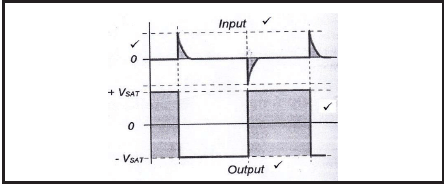 (4)
(4)
2.2 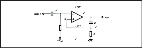 (4)
(4)
2.3 2.3.1 555 IC Astable multivibrator-circuit ✓ (1)
2.3.2 The circuit has no stable state in which to rest, its output continually oscillates between its two extreme maximums of +V and –V. ✓
In this circuit both Trigger Pin 2 and Threshold Pin 6 are connected to the top of the timing capacitor. ✓
This allows the circuit to repeatedly re-trigger, ? producing a continual stream of ‘high’ and ‘low’ pulses at its output. ✓ (4)
2.4 Widely used in the first stages of many radio receivers, especially in digital applications. ✓
In digital circuitry noise is often introduced into a system via switch bounce which can cause a number of unwanted voltage spikes to appear during switching-on period. ✓
Varying input waveforms, for example a sine wave can be changed into a square or rectangular wave. ✓
A signal can be successfully recovered using a Schmitt trigger even after having suffered severe distortion as the circuit will only sense a single level change, so eliminating all other noise spikes. ✓ (4)
2.5 2.5.1 Op-amp used as a summing amplifier-audio mixer ✓(1)
2.5.2 ?o?? = −( ?1 + ?2 + ?3)
= −(200 × 10−3 + 250 × 10−3 + 300 × 10−3)
= −750 × 10−3 ? or −0,75? (3)
2.6.1 This means that the circuit components values are large. ✓ (1)
2.6.2 In this circuit with a long time constant, a square wave would produce a long, slow triangular wave at its output. ✓(1)
2.7  (6)
(6)
2.8  (4)
(4)
2.9 Mono-stable multivibrator is the circuit that produces one pulse of a set length (time period T) ✓ in response to a trigger input such as a push button, it has one stable state. ✓ Bi-stable multivibrator is a circuit that changes states (flip) ✓ with the introduction of a trigger pulse, it has two stable states. ✓ (4)
2.10
2.10.1 Differentiator circuit ✓ (1)
2.10.2 Integrator circuit ✓ (1)
2.11 When the input is a positive-going voltage, ✓a current flows into the capacitor. ✓
The output voltage is directly proportional to the rate of change of the input voltage. ✓
The rate of change of charge is expressed as I = dQ ÷ dt amperes/second;✓ this is the mathematical expression ✓ that shows the change of charge (dQ) is being differentiated with the change in time (dt). ✓ (6)
2.12 The circuit operation relies on the charging rate of a capacitor and the resistor value. ✓✓ (2)
2.13 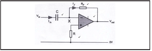 (4)
(4)
[58]
QUESTION 3: SEMICONDUCTOR DEVICES
3.1 An op amp must be able to raise and lower its output voltage above and below zero. ✓
To enable an op amp to function across its entire operating range it requires a second, negative power supply voltage. ✓
This will then enable its output to either rise above 0V in a positive direction or fall to below 0V in a negative direction. ✓ (3)
3.2 The entire circuit consists of hundreds of individual components reduced to easily fit onto the end of a finger. ✓
The chip is then mounted to its 8-pin case using fine gold wire to connect each of its points to their own external lead. ✓
The black resin case gives stability and strength to the unit with the external connecting pins being large enough to withstand the heat of being soldered to a PCB without the internal chip sustaining any damage. ✓ (3)
3.3
- Non-inverting ‘+’ ✓
- Inverting ‘-‘. ✓ (2)
3.4
- The amplifier circuit’s gain will be reduced. ✓
- The amplifier becomes much more stabilised. ✓ (2)
3.5  (3)
(3)
3.6
3.6.1 ??= 1 + R F
???
= 1 + 500 000
10 000
= 1 + 50
=51 (3)
3.6.2 Varying an input voltage will cause an output voltage swing (increase or decrease) ✓ (1)
3.7 Astable mode ✓ (1)
[18]
QUESTION 4: DIGITAL AND SEQUENTIAL DEVICES
4.1 Common anode ✓
Common cathode ✓ (2)
4.2 Polarisation ✓ (1)
4.3
4.3.1 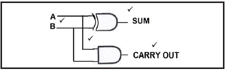 (4)
(4)
4.3.2
| INPUTS | OUTPUTS | ||
| A 0 0 1 1 | B 0 1 0 1 | SUM 0 1 1 0 | (CARRY) CO 0✓ 0✓ 0✓ 1 ✓ |
(4)
4.4 An encoder is designed to accept input data in decimal form and to convert this information into its binary form. ✓
A decoder is designed to convert a binary code into a recognisable decimal form, either as a digit or as a character. ✓ (2)
4.5 Sequential logic circuits rely on regular, ✓ clocked input pulses which cause them to operate on a step by step manner,✓relying on the flip flop as their basic operating element. ✓ (3)
4.6 4.6.1 The clocked RS Flip-Flop (Gated Latch). ✓ (1)
4.6.2 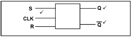 (3)
(3)
4.6.3
| MODE OF OPERATION | INPUTS | OUTPUTS | ||||
| CLOCK | S | R | Q | Q | ||
| NO CHANGE | 0 | 0 | NO CHANGE | ✓ | ||
| RESET | 0 | 1 | 0 | 1 | ✓ | |
| SET | 0 | 0 | 0 | 0 | ✓ | |
| HOLD | 1 | 1 | NO CHANGE | ✓ | ||
(4)
4.7 Asynchronous device is one that is free-running, ✓operating at its own pace ✓ and not relying on any externally added controlling pulse. ✓
Synchronous device is one that operates in step ✓with an externally added system’s clock pulses. ✓ (5)
4.8 4.8.1 Flip-flop FF0 has both of inputs J and K held permanently high ‘1’ so that it will toggle (change state) on each and every single clock pulse. ✓
FF1 will only toggle when the output Qo is high ‘1’ which is on every second clock pulse. ✓
FF2 will only become active and toggle when both outputs of the previous two stages Qo and Q1 are high ‘1’ which will be on every forth clock pulse.✓ (3)
4.8.2
| clk | Q2 | Q1 | Q0 | |
| 0 | 0 | 0 | 0 | |
| 1 | 1 | 1 | 1 | ✓ |
| 2 | 1 | 1 | 0 | |
| 3 | 1 | 0 | 1 | ✓ |
| 4 | 1 | 0 | 0 | |
| 5 | 0 | 1 | 1 | ✓ |
| 6 | 0 | 1 | 0 | |
| 7 | 0 | 0 | 1 | ✓ |
| 8 | 0 | 0 | 0 | |
| MSB | LSB |
(4)
4.9 Binary coded decimal ✓ It is a circuit that converts each individual decimal number ✓ in a sequence into a four-bit binary number. ✓ (3)
4.10 Full sequence counter is a counter that runs to its maximum count. ✓
Truncated is one that is modified to stop its count before reaching its maximum count. ✓ (2)
4.13 Set mode ✓
Reset mode ✓
No change or hold mode ✓ (3)
4.14 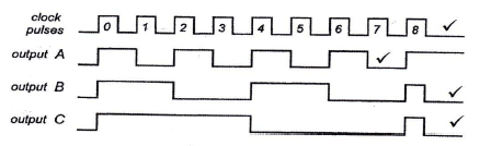 (4)
(4)
[58]
QUESTION 5: MICROCONTROLLERS
5.1 Microcontroller is an independent device, ✓ a computer on a chip that can perform a limited range of functions without needing to rely on other chips ✓ or devices. ✓(3)
5.2 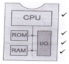 (4)
(4)
5.3 5.3.1 CPU: Central Processing Unit ✓- It does all the calculations and logic operations in the background, ✓allowing the programmes or software to function. ✓ (3)
5.3.2 RAM: Random Access Memory ✓- This is a fast, temporary memory ✓ that allows information to be stored and retrieved by the system as it operates. ✓ (3)
5.3.3 ROM: Read Only Memory ✓- This is where the start-up instructions ✓ are stored. ✓ (3)
5.4 A single microcontroller can replace a wide variety of traditional discrete electronic components like transistors, logic circuits and 555 timer ICs. ✓ They are smaller and cheaper and with fewer separate parts making them more reliable. ✓
Product assembly will be far simpler and therefore quicker and cheaper. ✓
Using microcontrollers can make products more flexible. (3)
5.5 Control bus ✓
Data bus ✓
Address bus ✓ (3)
5.6 Input sensors: switches, ✓ buttons,✓ movement detectors, distance sensors, movement sensors, light sensors, sound sensors and chemical sensors.
Output sensors (transducers): lights, ✓ displays, ✓ motors, servos, solenoids, pumps, sound speakers, hydraulic and pneumatic drives. (4)
5.7 Microprocessor is simply an IC which only has the Central Processing Unit (CPU) inside it. ✓
Microcontroller is a complete, small scale computer with all the necessary devices required to function, CPU, RAM, ROM and I/O embedded together on a single IC chip. ✓ (2)
5.8 Flow chart is a pictorial representation of an algorithm and the flow of a programme. ✓✓ (2)
5.9 
Award marks for correct: pictorial representation, sequence, decisions, activities and overall algorithm (5)
5.10 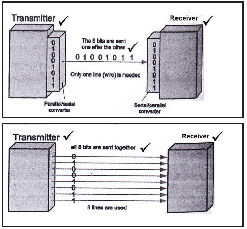 (6)
(6)
5.11 Program counter ✓
Current Instruction Register ✓
Memory Address register✓
Memory Data register (3)
5.12 Program is a sequence of instructions✓ that tells a computer how to do a task. ✓(2)
5.13 Register is a very fast working memory of a CPU. ✓✓ (2)
5.14
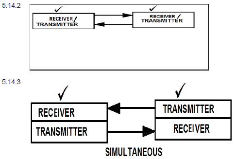
5.14.1 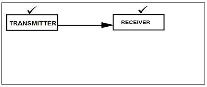 (2)
(2)
5.15 UART converts parallel data from the host processor into a serial data stream ✓ in preparation for transmission in a serial form. ✓ (2)
5.16 Discreet logic consists of many individual components, ✓ all mounted to a circuit board and interconnected to create a circuit. ✓ (2)
[58]
TOTAL: 200