ELECTRICAL TECHNOLOGY: POWER SYSTEMS GRADE 12 MEMORANDUM - NSC EXAMS PAST PAPERS AND MEMOS NOVEMBER 2018
Share via Whatsapp Join our WhatsApp Group Join our Telegram GroupELECTRICAL TECHNOLOGY: POWER SYSTEMS
GRADE 12
NSC EXAMS
PAST PAPERS AND MEMOS NOVEMBER 2018
INSTRUCTIONS TO THE MARKERS
- All questions with multiple answers imply that any relevant, acceptable answer should be considered.
- Calculations:
2.1 All calculations must show the formulae.
2.2 Substitution of values must be done correctly.
2.3 All answers MUST contain the correct unit to be considered.
2.4 Alternative methods must be considered, provided that the correct answer is obtained.
2.5 Where an incorrect answer could be carried over to the next step, the first answer will be deemed incorrect. However, should the incorrect answer be carried over correctly, the marker has to re calculate the values, using the incorrect answer from the first calculation. If correctly used, the candidate should receive the full marks for subsequent calculations.
2.6 Markers should consider that learner answers may deviate slightly from the guideline; depending on how and where in the calculation rounding off was used. - These marking guidelines are only a guide with model answers. Alternative interpretations must be considered and marked on merit. However, this principle should be applied consistently throughout the marking session at ALL marking centres.
MEMORANDUM
QUESTION 1: OCCUPATIONAL HEALTH AND SAFETY
1.1
- 'Major incident 'is an occurrence of catastrophic proportion✔ resulting from the use of plant and machinery from activities in the workplace. ✔
- Severe or serious injury or great damage to machinery and persons resulting from the use of plant or machinery in a workplace. (2)
1.2
- Manufacturers must ensure that products are safe✔
- Not permitting any employee to do any work or to produce any artefact unless precautionary measures are in place.✔
- Safe to use / without risk to health
- Safety feature
- Instructional manual
- In good condition without faults (2)
1.3
- 'Horseplay 'is an unsafe act because it is an inappropriate behaviour by learners✔ in the workshop that would compromise the safety✔ of themselves and others.
- It distracts others that could lead to accidents or incidents. (2)
1.4
- Do not touch the person. ✔
- Switch off the supply. ✔
- Help the person by removing him/her with a type of insulation material. (2)
1.5 Qualitative risk analysis defines the levels of threat ✔ and devises counter measures ✔ to eliminate possible risk. (2) [10]
QUESTION 2: RLC CIRCUITS
2.1 The total opposition to the flow of alternating current ✔ in a circuit comprising of resistance and reactance. ✔ (2)
2.2
2.2.1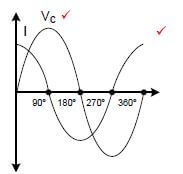 (2)
(2)
If the learner drew only one signal, it doesn’t show relation. (no marks)
2.2.2 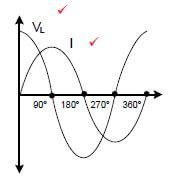 (2)
(2)
NOTE. If the learner drew only one signal, it doesn’t show relation. (no marks)
2.3
2.3.1
- C = 1
2 × π × f × XC
= 1 - 2 × π × 60 × 36
= 73,68μF ✔ (3)
NOTE. Note if the formula is copied directly from the formula sheet a mark must be awarded, there after the substitution, manipulation and the answer must be correct to receive 3 marks.
2.3.2
- L = XL
2 × π × 60
= 22
2 × π × 60
= 58,35 mH ✔ ✔ (3)
NOTE. Note if the formula is copied directly from the formula sheet a mark must be awarded, there after the substitution, manipulation and the answer must be correct to receive 3 marks.
2.3.3 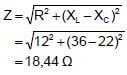 (3)
(3)
2.3.4
- I = VS
Z
= 60
18.44
= 3,25 A ✔ ✔ (3)
2.3.5
- Q = V × I × Sinθ
= 60 × 3,25 × Sin (50 º)✔
= 149,38 VA r ✔ (3)
2.4 The value of the inductive reactance will double/increase ✔ because the inductive reactance is directly proportional to the frequency ✔ of the supply voltage.
NOTE. If only the formula is given, no marks. If the formula is given as a reason, 1 mark will be awarded for the formula. (2)
2.5. The resonant frequency is the frequency at which the inductive reactance ✔ is equal to the capacitive reactance. ✔
NOTE. All characteristics of resonance explained correctly will be accepted. (2)
2.6
- XL = VS
IL
=100
2
= 50 Ω V (3) - XC = VS
IC
=100
6
= 16,67 Ω (3) - IX = IC - IL
= 6 - 2
= 4 A (3)
Note: If the learner sets one or a difference in reactive currents, the learner must get 3 points.  (3)
(3)
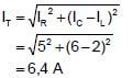 (3)
(3) 2.6.2 Phase angle is leading. ✔ (1)
2.7 A low value of resistance produces a high Q-factor ✔ which results in a low bandwidth ✔ and high selectivity. (2) [40]
QUESTION 3: THREE-PHASE AC GENERATION
3.1 120º ✔ (1)
3.2
3.2.1
- Apparent power is the product of the current and the voltage ✔ not considering reactance in an AC circuit. ✔
- Apparent power is the total power drawn from the supply. (2)
3.2.2 Power factor is the ratio ✔ of the active to the apparent power consumed in an AC circuit. ✔ (2)
3.3
- Thinner supply cables will be required.
- It will minimise the supply current.
- Cost of maintenance will be less (3)
3.4
3.4.1
- For alternator of similar frame size, single phase produces less power than three phase. ✔
- For the same amount of energy generated single phase power is relatively more expensive to generate than three phase. ✔
- Single phase supply can only supply power to single phase loads. ✔
- You can’t do load balancing with single phase loads.
- Single phase loads uses thicker supply cables. (3)
3.4.2 When the coils of a three phase alternator are connected in star, a neutral point is created ✔ and both line as well as phase voltages of different values are available. ✔ The neutral point can be earthed. (2)
3.5 The transmission voltage is inversely proportional to the current therefore by increasing the transmission voltage, ✔ the line current ✔ is decreased and the copper losses are reduced. (2)
3.6
3.6.1 Phase voltage
- VP = VL
√3
= 380
√3
= 219,39 V ✔ ✔ (3)
3.6.2 Line current to the load. 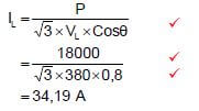 (3)
(3)
3.6.3 Apparent power 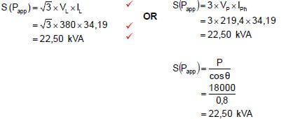 (3)
(3)
3.7
3.7.1 The total input power to the motor.
- PT = P1 + P2
= 1200 + 2300 ✔
= 3,5 kW ✔(3)
3.7.2
- The power factor can be determined. ✔
- The total input power can be measured in a star or delta connected system. ✔
- Only two wattmeters are required instead of three. ✔
- For a given supply voltage the line current can be determined without using an ammeter.
- Power in a balanced and unbalanced system can be measured.
- It is less complicated to connect two wattmeters than three wattmeters. (3) [30]
QUESTION 4: THREE-PHASE TRANSFORMERS
4.1
- Copper losses / I2R losses / heat losses.✔
- Iron losses / eddy current losses / Hysteresis losses / heat losses.✔
- Stray losses / Magnetic field losses.✔
- Dielectric losses. (3)
4.2 Delta-star is used for
- Power distribution in Commercial✔
- Power distribution in Industries ✔
- power distribution for domestic / step down 380 V to 220 V (2)
4.3
- It improves the insulation of the transformer.✔
- Conducts the heat away from the windings.✔ (2)
4.4
- When an alternating voltage is applied to the primary windings ✔ an alternating flux is created in the windings. ✔
- This flux will link with the secondary windings ✔ through the magnetic path of the iron core of the transformer ✔ inducing in it an emf of the same frequency. ✔
NOTE if only mutual induction is mentioned, 1 mark is awarded. (5)
4.5
- Transformers have no moving parts ✔ as a result less losses develops ✔ and it delivers a better power output. ✔
- Transformers are designed efficiently. (3)
4.6 To detect abnormal gas formation in the transformer ✔ and isolate it from the supply to prevent it from being damaged. ✔ (2)
4.7
4.7.1
- VP(S) = VL(S)
√3
= 380
√3
= 219,39V ✔ ✔ (3)
4.7.2
- TR = V1(P)
V2(P)
= 2200
219,39
= 10:1 ✔ ✔ (3)
4.7.3
- V1(P) = N1
V2(P) N2
N2 = 1500 × 219,39
2200
= 149,58 ✔ ✔ (3)
4.8
4.8.1 Is a step down transformer ✔ (because NP > NS) (1)
4.8.2 The secondary windings of the transformer are connected in star ✔ thereby creating a neutral point ✔ to supply single phase and three phase systems. ✔ (3) [30]
QUESTION 5: THREE-PHASE MOTORS AND STARTERS
5.1
5.1.1 1,3 A ✔ (1)
5.1.2 The motor can be used in South Africa because of the supply voltage of 380 V ✔ with a frequency of 50 Hz. ✔ (2)
5.1.3 The 7,5 kW signifies the rated output power ✔ the motor can deliver to drive the load. (1)
5.1.4
- p = 60 × f
ns
= 60 × 50
1500
= 2 polepairsper phase ✔ ✔
∴ Total numberof poles 2 × 2 × 3 ✔
= 12 poles ✔ (5)
5.1.5
- Pin = Pout + Plosses
= 7500 + 1200
= 8,7 kW ✔
η = Pout × 100
Pin
= 7500 × 100 ✔
8700
= 86,21 % (5)
Alternative answer
- η = Pout × 100
Pout + Plosses
= 7500 × 100
7500 + 1200
= 86,21 % ✔✔
5.2
- No-volt protection prevents a motor from restarting ✔ after a power failure ✔ to protect the operator. ✔ (3)
- If the supply voltage drops below a prescribed value, it will switch off the supply.
5.3
- By changing any two✔ of the three supply lines. ✔ (2)
- NOTE mentioning the colour of the lines are accepted.
5.4 Check if the:
- End plates are securely fastened. ✔
- Frame has any cracks. ✔
- Shaft turns freely.
- Bearing works smoothly when the shaft is turned. Cooling fan / fin (2)
5.5
5.5.1 Forward reverse control circuit. ✔ (1)
5.5.2
- In elevators to change the direction of the motor. ✔ (1)
- Conveyor belts
- Lathe
5.5.3The purpose of the overload is to disconnect the supply from the motor ✔, when the current exceeds the pre-set value. ✔ (2)
5.5.4
- When the start button is pressed, current will flow in the circuit and MC1/FWD becomes energised. ✔
- When MC1/FWD is energised, MC1/NO closes and MC1/NC opens and the motor will run forward. ✔
- When the stop button is pressed MC1/FWD de-energised opening contact MC1/NO and closing MC1/NC and the motor stops running. ✔
- When the reverse start button is pressed, current will flow in the circuit and MC2/REV becomes energised. ✔
- When MC2/REV is energised, MC2/NO closes and MC2/NC opens and the motor will run in the reverse. ✔ (5) [30]
QUESTION 6: PROGRAMMABLE LOGIC CONTROLLERS (PLCs)
6.1
- Requires regular maintenance. ✔
- It takes time to locate a fault. ✔
- It takes longer to re-wire the system when compared to the reprogramming of the PLC. ✔ (3)
6.2
- Input scan/input module .✔ (checks input device state)
- Process ✔ (complete instruction)
- Output module ✔ (update) (3)
6.3 'Scan time' is the time the PLC takes to complete ✔ one scan cycle, ✔ processing in each of the three most important steps. (2)
6.4
6.4.1 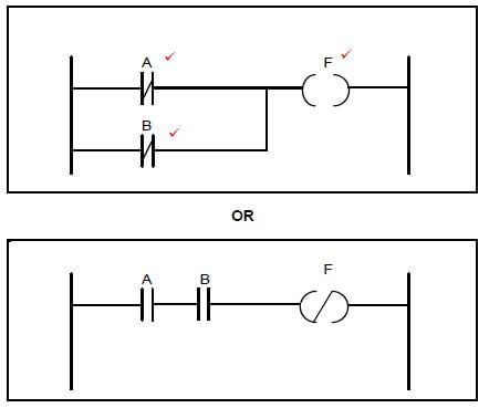 (3)
(3)
6.4.2 (4)
A | B | F |
0 | 0 | 1✔ |
0 | 1 | 1✔ |
1 | 0 | 1✔ |
1 | 1 | 0✔ |
TABLE 6.4.2
6.5 A
- PLC is an industrial computing device that is programmed ✔ to perform a number of tasks as per instruction ✔ and to control various types of machines and processes. ✔ (3)
OR - A PLC is a programmable device capable of interpreting logic for the purpose of controlling a series of output after scanning inputs state and applying the programmed logic.
6.6
6.6.1
- Light sensor. ✔
- Level sensor. ✔
- Overload sensor. ✔
- Temperature sensor. (3)
6.6.2
- A computing device (microprocessors, computers, and logic units) can only interpret the electronic digital/discrete language instructions for processing, monitoring and controlling. ✔ other than an analogue languages, which are highly exposed to noise. ✔ and may cause wrong readings because of its limitations in accuracy ✔and unpredictable behaviour in a control system which might compromise the intended output .✔ (4)
OR - Analogue signals are sampled and converted to definitive digital steps or values to eliminate or avoid any possible misinterpretations or fault state that may arise from noise or interference that could be superimposed on the input signal.
6.7 The output of the PLC sends a positive signal (high logic) to its internal output relay. ✔ This energizes the relay coil which closes its contacts ✔ to drive the motor. ✔ (3)
6.8 The purpose of the timer function is to activate or deactivate a device ✔ after or before a pre-set interval of time. ✔ (2) OR The purpose of the timer function is to run an operation for a predetermined period of time.
6.9 The concept of latching makes it possible for circuit to be triggered 'on'✔ and remain 'on'✔ regardless of whether the activating trigger has been removed.✔ (3)
6.10
6.10.1
- Automatic star delta starter. ✔
- Star delta starter (1)
6.10.2 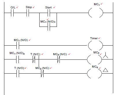 (13)
(13)
Alternative methods are accepted IF the circuit is working correctly.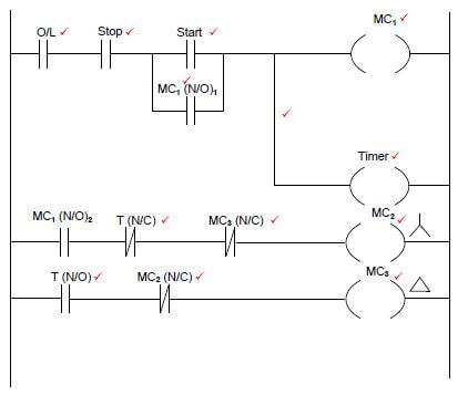
6.10.3 The function of the MC1/NO1 in ladder logic control circuit is to Latch the circuit ✔ and keep the program running even after the start button is released. ✔ (2)
6.10.4 The purpose of MC3 NC is to interlock ✔ and prevents ✔ MC2 from engaging when MC3 is engaged in delta. (2)
6.11
- Induction motors. ✔
- AC synchronous motors. ✔
- AC asynchronous motors. ✔
- DC motors (3)
6.12 A process of changing the frequency of the input voltage ✔ to change the speed and torque of the motor. ✔ (2)
6.13 The purpose of the braking resistor is to stop or slow down the motor through absorption of excess energy ✔ and converting excess energy to heat while in motion by transforming kinetic energy back into electrical energy ✔ through the process of regenerative breaking. (2)
6.14
- The function of the VSD is to control the speed of an AC motor ✔ by varying the frequency of the voltage supplied ✔ to the motor.
- The function of the VSD is to control the speed of a DC motor by varying the voltage supplied to the motor. (2) [60]
TOTAL: 200