ELECTRICAL TECHNOLOGY: POWER SYSTEMS GRADE 12 QUESTIONS - NSC EXAMS PAST PAPERS AND MEMOS NOVEMBER 2018
Share via Whatsapp Join our WhatsApp Group Join our Telegram GroupELECTRICAL TECHNOLOGY: POWER SYSTEMS
GRADE 12
NSC EXAMS
PAST PAPERS AND MEMOS NOVEMBER 2018
INSTRUCTIONS AND INFORMATION
- This question paper consists of SIX questions.
- Answer ALL the questions.
- Answer QUESTIONS 2.2.1 and 2.2.2 on the attached ANSWER SHEET.
- Write your CENTRE NUMBER and EXAMINATION NUMBER on the ANSWER SHEET and hand it in with your ANSWER BOOK, whether you have used it or not.
- Sketches and diagrams must be large, neat and fully labelled.
- Show ALL calculations and round off answers correctly to TWO decimal places.
- Number the answers correctly according to the numbering system used in this question paper.
- You may use a non-programmable calculator.
- Show the units for ALL answers of calculations.
- A formula sheet is provided at the end of this question paper.
- Write neatly and legibly.
QUESTIONS
QUESTION 1: OCCUPATIONAL HEALTH AND SAFETY (GENERIC)
1.1 Define the term major incident with reference to the Occupational Health and Safety Act, 1993 (Act 85 of 1993). (2)
1.2 State TWO general duties of manufacturers with regard to a product that will be used at the workplace. (2)
1.3 Explain why horseplay is an unsafe act in the workshop. (2)
1.4 State TWO procedures to protect yourself when helping a person who is being shocked by electricity. (2)
1.5 Define the term qualitative risk analysis. (2) [10]
QUESTION 2: RLC CIRCUITS (GENERIC)
2.1 Define the term impedance with reference to RLC circuits. (2)
2.2 Illustrate the phase relationship between current and voltage by drawing the waveforms of the following circuits on the ANSWER SHEET:
2.2.1 Pure capacitive circuit (2)
2.2.2 Pure inductive circuit (2)
2.3 FIGURE 2.3 below shows an RLC series circuit that consists of a 12 Ω resistor, an inductor with a reactance of 22 Ω and a capacitor with a reactance of 36 Ω, all connected across a 60 V/60 Hz supply. Answer the questions that follow. 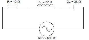
FIGURE 2.3: RLC SERIES CIRCUIT
Given:
R = 12 Ω
XL = 22 Ω
XC = 36 Ω
VS = 60 V
f = 60 Hz
Calculate the:
2.3.1 Capacitance of the capacitor (3)
2.3.2 Inductance of the inductor (3)
2.3.3 Impedance of the circuit (3)
2.3.4 Total current through the circuit (3)
2.3.5 Reactive power at a phase angle of 50° (3)
2.4 Explain how the value of the inductive reactance will be affected if the supply frequency is doubled. (2)
2.5 Define the term resonant frequency. (2)
2.6 Refer to FIGURE 2.6 and answer the questions that follow. 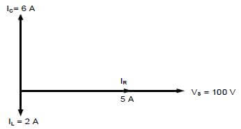
FIGURE 2.6: RLC PHASOR DIAGRAM
2.6.1 Calculate the following:
- Inductive reactance (3)
- Capacitive reactance (3)
- Reactive current (3)
- Total current (3)
2.6.2 State whether the phase angle is lagging or leading. (1)
2.7 Describe how a low resistance value affects the bandwidth of an LC tuned circuit. (2) [40]
QUESTION 3: THREE-PHASE AC GENERATION (SPECIFIC)
3.1 State the size of the angles between the phases of a balanced three-phase AC generated waveform. (1)
3.2 Define the following terms:
3.2.1 Apparent power (2)
3.2.2 Power factor (2)
3.3 State THREE advantages for the supplier when the power factor improves. (3)
3.4 With reference to three-phase power generation:
3.4.1 State THREE disadvantages of single-phase AC generation. (3)
3.4.2 Explain the advantage of connecting a three-phase alternator in star. (2)
3.5 Explain how copper losses are reduced in overhead transmission lines. (2)
3.6 A 380 V three-phase system supplies a star-connected inductive load. The input power to the load is 18 kW with a lagging power factor of 0,8.
Given:
VL = 380 V
Pin = 18 kW
Cos θ = 0,8 lagging
Calculate the:
3.6.1 Phase voltage (3)
3.6.2 Line current to the load (3)
3.6.3 Apparent power (3)
3.7 The two-wattmeter method is used to measure power of a three-phase motor. The readings on the wattmeters are 1,2 kW and 2,3 kW respectively. Answer the questions that follow.
Given:
P1 = 1,2 kW
P2 = 2,3 kW
3.7.1 Calculate the total input power to the motor. (3)
3.7.2 State THREE advantages of the two-wattmeter method over the three-wattmeter method. (3) [30]
QUESTION 4: THREE-PHASE TRANSFORMERS (SPECIFIC)
4.1 Name THREE losses that occur in transformers. (3)
4.2 State TWO applications of a delta-star transformer. (2)
4.3 State TWO functions of the oil used in transformers. (2)
4.4 Describe the operation of a transformer. (5)
4.5 Explain why transformers have a better efficiency in comparison to other machines. (3)
4.6 State the purpose of the Buchholz relay in transformers. (2)
4.7 A three-phase transformer with 1 500 primary turns is connected in delta-star to a supply voltage of 2,2 kV. The primary line current is 30 A and the secondary line voltage is 380 V with a power factor of 0,9.
Given:
NP = 1 500 turns
VP = 2,2 kV
I L(P) = 30 A
V L(S) = 380 V
Cos θ = 0,9 lagging
Calculate the:
4.7.1 Secondary phase voltage (3)
4.7.2 Transformation ratio (3)
4.7.3 Number of secondary turns (3)
4.8 A three-phase transformer with a turns ratio of 30 : 1 is connected in delta star. Answer the questions that follow.
4.8.1 Determine whether the transformer is a step-down or a step-up transformer. (1)
4.8.2 Describe why the transformer can be used for distributing electrical power to domestic and industrial loads. (3) [30]
QUESTION 5: THREE-PHASE MOTORS AND STARTERS (SPECIFIC)
5.1 TABLE 5.1 below shows the name plate of a three-phase induction motor. Answer the questions that follow.
TABLE 5.1: NAME PLATE OF A THREE-PHASE INDUCTION MOTOR
MOTOR MANUFACTURER SPECIFICATION | |
Phase | 3 |
Voltage | 380 V |
Current | 1,3 A |
Speed | 1 500 r/min |
Power | 7,5 kW |
Frequency | 50 Hz |
Cos θ | 0,8 lagging |
Frame No. | 22SP27 |
5.1.1 State the amount of current the motor will draw from the supply at full load. (1)
5.1.2 Explain why the motor is suitable for use in South Africa. (2)
5.1.3 State what the 7,5 kW on the name plate indicates. (1)
5.1.4 Determine the total number of poles. (5)
5.1.5 Calculate the efficiency of the motor at full load if the total loss is 1,2 kW. (5)
5.2 Explain the purpose of no-volt protection with reference to motor control circuits. (3)
5.3 Explain how the direction of rotation of a three-phase induction motor can be changed. (2)
5.4 State TWO mechanical inspections that must be carried out on an induction motor before commissioning. (2)
5.5 Refer to the control circuit diagram in FIGURE 5.5 and answer the following questions. 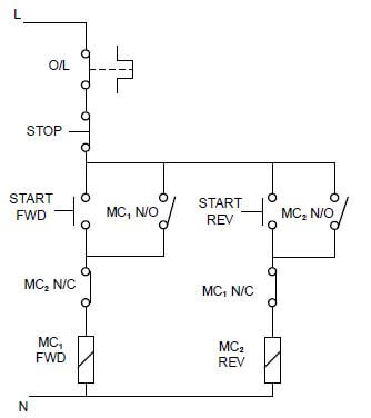
FIGURE 5.5: CONTROL CIRCUIT
5.5.1 Identify the control circuit in FIGURE 5.5. (1)
5.5.2 State ONE application of the control circuit. (1)
5.5.3 State the purpose of the overload relay. (2)
5.5.4 Describe the operation of the control circuit. (5) [30]
QUESTION 6: PROGRAMMABLE LOGIC CONTROLLERS (PLCs) (SPECIFIC)
6.1 State THREE disadvantages of hard wiring. (3)
6.2 Name the THREE steps that a PLC has to undergo to complete one programmed scan cycle. (3)
6.3 Explain the term scan time with reference to the scan cycle of a PLC. (2)
6.4 Refer to FIGURE 6.4 below and answer the questions that follow. ![]()
FIGURE 6.4: NAND gate
6.4.1 Draw the ladder logic diagram. (3)
6.4.2 Draw the truth table for the NAND gate. (4)
6.5 Describe how a PLC achieves its function. (3)
6.6 With reference to analogue and digital inputs:
6.6.1 Give THREE examples of analogue input devices. (3)
6.6.2 Explain why an analogue input may be converted to a digital input. (4)
6.7 Describe how a PLC uses a relay to drive a motor. (3)
6.8 State the purpose of the timer function. (2)
6.9 Explain the latching concept with reference to retaining circuits. (3)
6.10 Refer to FIGURE 6.10 below and answer the questions that follow. 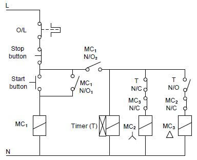
FIGURE 6.10: CONTROL CIRCUIT
6.10.1 Identify the control circuit in FIGURE 6.10. (1)
6.10.2 Draw a ladder logic diagram that executes the same function as the one in FIGURE 6.10. (13)
6.10.3 State the function of the MC1/NO1 as used in ladder logic circuits. (2)
6.10.4 State why the N/C contact of MC3 is connected in series with the star contactor. (2)
6.11 Name THREE types of motors used with variable speed drives (VSD). (3)
6.12 Explain voltage frequency control with reference to VSD. (2)
6.13 Explain the purpose of the braking resistor with reference to regenerative braking. (2)
6.14 Explain the function of the VSD when used in motors. (2) [60]
TOTAL: 200
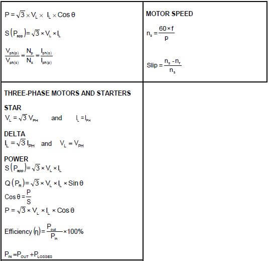
FORMULA SHEET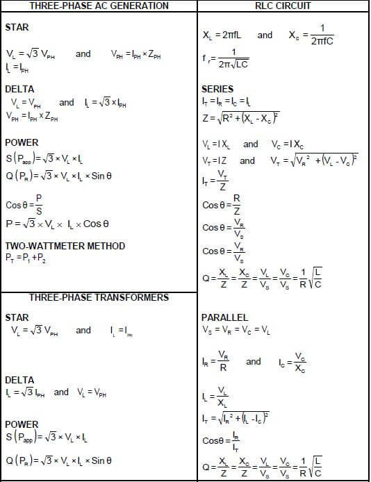
EXAMINATION NUMBER: |
CENTRE NUMBER: |
ANSWER SHEET
QUESTION 2.2 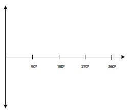
FIGURE 2.2.1 (2) 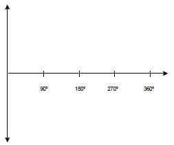
FIGURE 2.2.2 (2)