CIVIL TECHNOLOGY: WOODWORKING GRADE 12 QUESTIONS - NSC EXAMS PAST PAPERS AND MEMOS NOVEMBER 2018
Share via Whatsapp Join our WhatsApp Group Join our Telegram GroupCIVIL TECHNOLOGY: WOODWORKING
GRADE 12
NSC EXAMS
PAST PAPERS AND MEMOS
NOVEMBER 2018
REQUIREMENTS:
- Drawing instruments
- A non-programmable calculator
- ANSWER BOOK
INSTRUCTIONS AND INFORMATION
- This question paper consists of SIX questions.
- Answer ALL the questions.
- Answer each question as a whole. Do NOT separate subsections of questions.
- Start the answer to EACH question on a NEW page.
- Do NOT write in the margins of the ANSWER BOOK.
- You may use sketches to illustrate your answers.
- Write ALL calculations and answers in the ANSWER BOOK or on the attached ANSWER SHEETS as required.
- Use the mark allocation as a guide to the length of your answers.
- Make drawings and sketches in pencil, fully dimensioned and neatly finished off with descriptive titles and notes to conform to the SANS/SABS Code of Practice for Building Drawings.
- For the purpose of this question paper, the size of a brick should be taken as 220 mm x 110 mm x 75 mm.
- Use your own discretion where dimensions and/or details have been omitted.
- Answer QUESTIONS 2, 3.5, 5.9, 6.3 and 6.7 on the attached ANSWER SHEETS using drawing instruments, where necessary.
- Write your CENTRE NUMBER and EXAMINATION NUMBER on every ANSWER SHEET and hand them in with your ANSWER BOOK, whether you have used them or not.
- Drawings in the question paper are NOT to scale due to electronic transfer.
- Google Images was used as the source of all photographs and pictures.
QUESTIONS
QUESTION 1: OHSA, MATERIALS, TOOLS, EQUIPMENT AND JOINING (GENERIC)
Start this question on a NEW page.
1.1 Choose a description from COLUMN B that matches an item in COLUMN A. Write only the letter (A–G) next to the question numbers (1.1.1 to 1.1.5) in the ANSWER BOOK, e.g. 1.1.6 H.
COLUMN A | COLUMN B |
1.1.1 Sole plate |
(5 x 1) (5) |
1.2 Describe TWO safety precautions that must be adhered to when working on a scaffold. (2)
1.3 What is the purpose of the guard rail of a scaffold in terms of safety? (2)
1.4 Explain the purpose of painting. (2)
1.5 Describe ONE advantage of the curing process of concrete. (1)
1.6 FIGURE 1.6 below shows a tool that is used in the building construction industry. 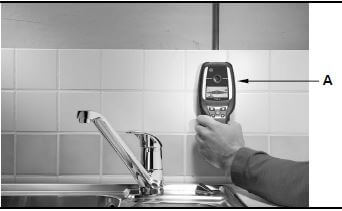
FIGURE 1.6
1.6.1 Identify tool A. (1)
1.6.2 Explain TWO uses of tool A. (2)
1.6.3 Explain why the batteries should be removed from the tool if the tool is not going to be used for a long time. (1)
1.7 FIGURE 1.7 below shows joining fixtures that are used on building sites and in workshops. 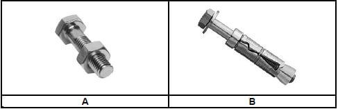
FIGURE 1.7
1.7.1 Identify fastener A and fastener B. (2)
1.7.2 Explain ONE use of fastener A and fastener B respectively. (2) [20]
QUESTION 2: GRAPHICS AS METHOD OF COMMUNICATION (GENERIC)
FIGURE 2 on the next page shows different drawings that appear on a building plan. Analyse the drawings and complete the table on ANSWER SHEET 2. 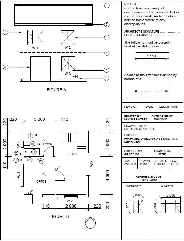
FIGURE 2 [40]
QUESTION 3: CASEMENTS, CUPBOARDS, WALL-PANELLING AND QUANTITIES (SPECIFIC)
Start this question on a NEW page.
3.1 Give ONE word/term for EACH of the following descriptions by choosing a word/term from the list below. Write only the word/term next to the question numbers (3.1.1 to 3.1.5) in the ANSWER BOOK, e.g. 3.1.6 Casement.
| fanlight; 600 mm–650 mm; skirting; tongue and groove boards; frame head; 520 mm–570 mm; window; cornice; melamine boards; drip groove |
3.1.1 Boards that are usually made of knotty pine and fit easily into one another by means of a specific feature on each side of the board (1)
3.1.2 The recommended depth of free-standing cupboards (1)
3.1.3 To close the opening between the wall and the ceiling (1)
3.1.4 Prevent rainwater from being blown into the casement and penetrating the room (1)
3.1.5 The small window that is built above the opening of a door or window (1)
3.2 FIGURE 3.2 below shows an external elevation of a double casement with fanlights. Study the picture and answer the questions that follow. 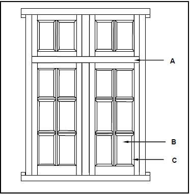
FIGURE 3.2
3.2.1 What type of material can be used for part A and part B respectively? (2)
3.2.2 Explain the purpose of C. (1)
3.3 FIGURE 3.3 below shows the inside of a built-in cupboard without doors. Study the drawing and answer the questions that follow. 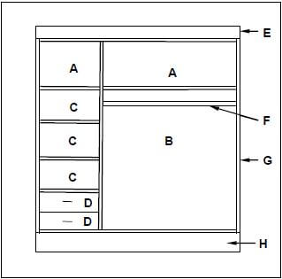
FIGURE 3.3
3.3.1 A well-designed cupboard should consist of four main parts/units. Name parts/units A to D in the drawing above. (4)
3.3.2 Justify the use of melamine rather than plain chipboard for the inside of a built-in cupboard. (1)
3.3.3 Identify parts E to H. (4)
3.4 FIGURE 3.4 below shows the sectional view of a tongue and groove wall panel from the floor to the ceiling, fastened to a 110 mm thick wall. Study the drawing and answer the questions that follow. 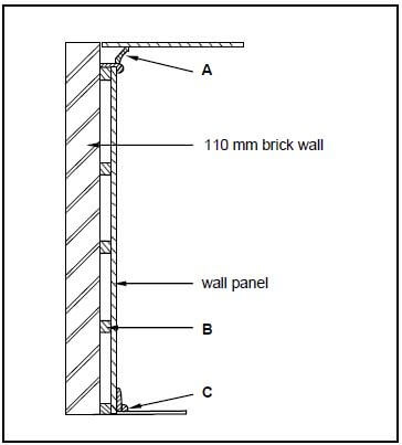
FIGURE 3.4
3.4.1 Identify parts A to C. (3)
3.4.2 Give TWO reasons for panelling a wall. (2)
3.5 FIGURE 3.5 below shows the floor plan of a building with a gable roof. The external measurements are 9 000 mm x 5 000 mm. 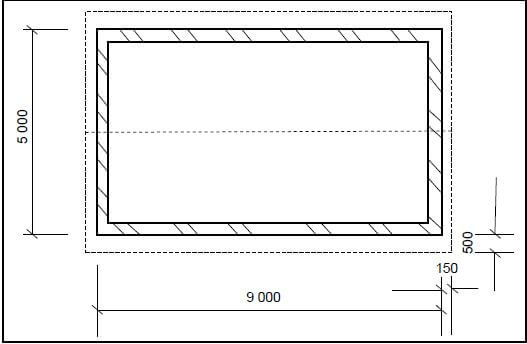
FIGURE 3.5
Use the following specifications:
- Walls are 220 mm thick
- Type of roof – South African (Howe) roof
- Centre-to-centre spacing between purlins = 900 mm
- True length of rafter (principal rafter) = 3 600 mm
Use ANSWER SHEET 3.5 and calculate the following:
3.5.1 Length of the wall plates (4)
3.5.2 Number of purlins needed (4) [30]
QUESTION 4: ROOFS, CEILINGS, TOOLS AND EQUIPMENT, AND MATERIALS (SPECIFIC)
Start this question on a NEW page.
4.1 Choose a description from COLUMN B that matches an item in COLUMN A. Write only the letter (A–H) next to the question numbers (4.1.1 to 4.1.5) in the ANSWER BOOK, e.g. 4.1.6 J.
COLUMN A | COLUMN B |
4.1.1 King post 4.1.2 Purlin 4.1.3 Eaves 4.1.4 Jig saw 4.1.5 Wax |
(5 x 1) (5) |
4.2 FIGURE 4.2 below shows a pictorial view of a roof with a hipped end and a gable end with a valley. The roof will be covered with corrugated iron sheeting. Study FIGURE 4.2 below and answer the questions that follow. 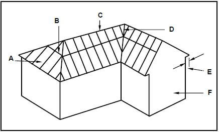
FIGURE 4.2
4.2.1 Identify members A to F. (6)
4.2.2 What are the breadth and thickness of part B in mm? (1)
4.3 Explain why the corrugated iron sheeting is protruding 50 mm over the end of the rafter. (1)
4.4 Explain TWO characteristics of a good roof covering. (2)
4.5 Differentiate between the profiles of IBR sheeting and corrugated iron sheeting by means of single-line sketches. Name EACH sketch. (4)
4.6 Describe TWO advantages a steel roof sheet. (2)
4.7 Explain the consequences if roof underlay is not installed under roof covering. (2)
4.8 FIGURE 4.8 below shows a sectional view of a conventional trap door. Study the sketch en give ONE word/term for each letter (A to D) by choosing a word/term from the list below. Write only the word/term next to the letter (A–D) in the ANSWER BOOK, e.g. E – Rafter.
| tie beam; rafter; strut; brandering; trap door; ceiling board; cover strip |
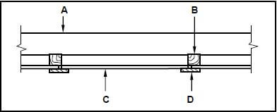
FIGURE 4.8 (4)
4.9 FIGURE 4.9 below shows two woodworking machines. Study the pictures and answer the questions that follow. 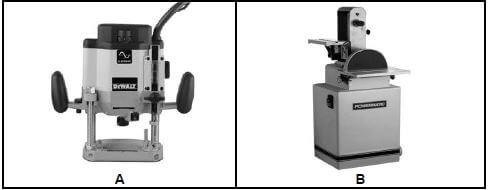
FIGURE 4.9
4.9.1 Identify machines A and B. (2)
4.9.2 Recommend TWO ways of storing A after use. (2)
4.9.3 What aspects would you take into consideration when taking care of B? (2)
4.9.4 Name THREE types of woodworking machines that you can use to cut wood. (3)
4.10 FIGURE 4.10 below shows two graded wooden planks. 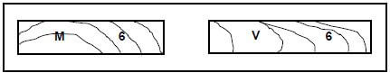
FIGURE 4.10
4.10.1 Explain the grading of each plank as indicated by the letters. (2)
4.10.2 Explain the number on each plank. (1)
4.10.3 Name the symbol that indicates that grading has been done, but which is missing on each plank. (1) [40]
QUESTION 5: CENTERING, FORMWORK, SHORING AND GRAPHICS AS MEANS OF COMMUNICATION (SPECIFIC)
Start this question on a NEW page.
5.1 FIGURE 5.1 below shows a vertical sectional view through formwork for two concrete beams. Study FIGURE 5.1 and identify members A to D. Write only the answer next to the letter (A–D) in the ANSWER BOOK, e.g. E – Rib. 
FIGURE 5.1 (4)
5.2 Recommend FOUR wooden board products that can be used as sides for formwork. (4)
5.3 Explain the purpose of folding wedges during the construction of formwork. (3)
5.4 Explain the reason why the bottom soffit board in the construction of formwork for a concrete beam is thicker than the sides of the formwork. (1)
5.5 FIGURE 5.5 below shows a pictorial view of closed laggings. Study the picture and answer the questions that follow. 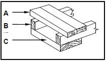
FIGURE 5.5
5.5.1 Identify parts A to C. (3)
5.5.2 Explain ONE use of A if it is used in a closed position, as shown in FIGURE 5.5. (1)
5.5.3 Name ONE other position in which A can be used in laggings. (1)
5.6 Explain ONE use of the following shores:
5.6.1 Dead shore (1)
5.6.2 Double-flying shore (1)
5.7 Describe the function of the following components of a dead shore:
5.7.1 Steel dog (1)
5.7.2 Prop/Strut (1)
5.7.3 Sole plate (1)
5.8 At what angle must the braces above and beneath the horizontal shores be placed on a double-flying shore? (1)
5.9 Use ANSWER SHEET 5.9 and draw a neat line diagram of a couple roof truss on top of the indicated walls. The slope of the roof truss is 45°.
Show the following on the drawing:
- The span by means of dimension lines
- Wall plates
- Rafters
- Ridge beam
- Slope of the roof (7) [30]
QUESTION 6: SUSPENDED FLOORS, STAIRCASES, IRONMONGERY, DOORS AND JOINING (SPECIFIC)
Start this question on a NEW page.
6.1 Various options are given as possible answers to the following questions. Choose the answer and write only the letter (A–D) next to the question numbers (6.1.1 to 6.1.5) in the ANSWER BOOK, e.g. 6.1.6 C.
6.1.1 The spacing between the floor joists …
- will not affect the strength of the suspended floor.
- depends on the thickness of the joist.
- depends on the availability of timber planks.
- should be 400 mm to 600 mm from centre to centre. (1)
6.1.2 Suspended timber floors …
- can only be used on upper levels.
- can be placed directly on the floor.
- can be used on ground levels or upper levels.
- do not need any air bricks or vents underneath the floor. (1)
6.1.3 Floorboards should have a ...
- mortice and tenon joint along the edges.
- tongue along the one edge and a groove along the other edge.
- clearance of at least 50 mm from the plaster or the wall.
- width of at least 40 mm and not exceed 180 mm. (1)
6.1.4 A framed ledged and braced batten door …
- can be used for back doors (kitchen).
- has solid panels.
- has braces of 40 mm.
- can be made of board products. (1)
6.1.5 A three-panel door with raised and fielded panels …
- is ideal for the front entrance of a house.
- should not be less than 1 000 mm away from the wall.
- should have a total length of 1 800 mm.
- has no lock rail. (1)
6.2 At suspended floors of multistorey buildings there are two methods that are commonly used to fix the ends of the floor joist to the walls.
Differentiate between the TWO methods by means of neat freehand sketches. Write the name of the method below EACH drawing. (4)
6.3 FIGURE 6.3 on ANSWER SHEET 6.3 shows the foundation, NGL and the starting point of the wall of a brick pier. Use ANSWER SHEET 6.3 and draw a neat sketch, in good proportion, of a sectional view of a suspended timber floor that is supported by brick piers.
Show the following on your drawing:
- One-brick pier
- DPC
- Antguard
- Bearer
- Part of the floor joist on both sides of the brick pier
- Floor boards (6)
6.4 Draw a neat line diagram, in good proportion, of a staircase in your ANSWER BOOK.
Show the following on your drawing:
- Landing
- Rise
- Tread/Going
- Newel/Newel post
- Handrail (5)
6.5 Explain the purpose of the landing in a staircase. (2)
6.6 The lock is an important part of a door. On which part of a three-panel door or door frame will you mount the following parts of a lock?
6.6.1 Box lock/Casing (1)
6.6.2 Back plate/Striker plate (1)
6.6.3 Keeper (1)
6.6.4 Night lock (1)
6.7 Use ANSWER SHEET 6.7 and draw neat top views of a raised panel and a raised and fielded panel in the given spaces. (4)
6.8 Explain the purpose of opening A in FIGURE 6.8 below. 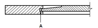
FIGURE 6.8 (1)
6.9 Study FIGURE 6.9 below which shows the inside bottom corner of a framed ledge and braced batten door. Identify members A to C. 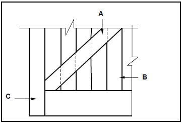
FIGURE 6.9 (3)
6.10 Use the descriptions below and explain the method of joining the components. Write only the answer next to the question number in your ANSWER BOOK.
6.10.1 Door to door frame (1)
6.10.2 Ceiling board to ceiling battens/brandering (1)
6.10.3 Brandering to tie beam (1)
6.10.4 Adjacent members of a roof truss (1)
6.11 State TWO methods that can be used to fix opening window frames to the jambs of casements. (2) [40]
TOTAL: 200
EXAMINATION NUMBER: |
CENTRE NUMBER: |
ANSWER SHEET 2
NO. | QUESTIONS | ANSWERS | MARKS |
1 | Identify FIGURE A. | 1 | |
2 | Identify FIGURE B. | 1 | |
3 | Identify number 4. | 1 | |
4 | Identify number 5. | 1 | |
5 | Identify number 9. | 1 | |
6 | Identify number 10. | 1 | |
7 | Identify number 11. | 1 | |
8 | On what date was the plan printed? | 1 | |
9 | Who drew the building plan? | 1 | |
10 | Name the feature in the column for the notes in FIGURE 2 that must be installed in front of the sliding door. | 1 | |
11 | Name the feature in the column for the notes in FIGURE 2 that must give access to the first floor. | 1 | |
12 | Identify the type of roof that is used for the building in FIGURE A. | 1 | |
13 | Explain the purpose of number 1. | 1 | |
14 | Explain the purpose of number 2. | 1 |
15 | Explain the abbreviation FFL at number 6. | 1 | |
16 | Explain the purpose of number 7. | 1 | |
17 | Explain the meaning of the arrow on the feature that must be installed in front of the sliding door. | 1 | |
18 | Explain what is meant by 1 : 10 indicated on the symbol in the notes. | 1 | |
19 | Which room will feature 15 serve? | 1 | |
20 | Explain the short dashed lines on the windows. | 1 | |
21 | Deduce the height of window 2 from the window schedule. | 1 | |
22 | Deduce the width of window 3 from the window schedule. | 1 | |
23 | On what elevation of the building is the bathroom window situated? | 1 | |
24 | Differentiate between component number 3 and component number 8. | 2 | |
25 | Differentiate between the light in the lounge and the light in the bathroom. | 2 | |
26 | Recommend a suitable floor covering for the bathroom. | 1 | |
27 | Recommend an appropriate scale to which FIGURE A should be drawn, according to SANS. | 1 | |
28 | Recommend an alternative sanitary fitment to replace number 11 that will serve a similar purpose. | 1 |
29 | Calculate the internal area of the office in m². Show ALL calculations. | 3 | |
30 | Calculate the perimeter of the building. Show ALL calculations. | 7 | |
TOTAL | 40 |
EXAMINATION NUMBER: |
CENTRE NUMBER: |
ANSWER SHEET 3.5 (8)
A | B | C | D | |
| 3.5.1 | Internal measurements of long walls: | |||
= _________ - _________ = | ||||
Length of wall plates needed: | ||||
__/ | _______ | _______ | ||
| 3.5.2 | Number of purlins needed | |||
Number of purlins = Length of rafter + 1 | ||||
= __________ | ||||
= __________ | ||||
= purlins | ||||
EXAMINATION NUMBER: |
CENTRE NUMBER: |
ANSWER SHEET 5.9 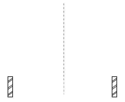
ASSESSMENT CRITERIA | MARK | CANDIDATE'S MARK |
Span | 1 | |
Wall plates | 2 | |
Rafters | 2 | |
Ridge beam | 1 | |
Slope of roof | 1 | |
TOTAL: | 7 |
EXAMINATION NUMBER: |
CENTRE NUMBER: |
ANSWER SHEET 6.3 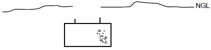
DRAWING NOT TO SCALE
ASSESSMENT CRITERIA | MARK | CANDIDATE'S MARK |
ONE one-brick pier | 1 | |
NGL | 1 | |
Ant guard | 1 | |
Bearer | 1 | |
Joist | 1 | |
Floor boards | 1 | |
TOTAL: | 6 |
EXAMINATION NUMBER: |
CENTRE NUMBER: |
ANSWER SHEET 6.7 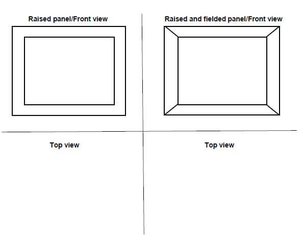
DRAWING NOT TO SCALE
ASSESSMENT CRITERIA | MARK | CANDIDATE'S MARK |
Raised panel top view | 2 | |
Raised and fielded panel top view | 2 | |
TOTAL: | 4 |