FITTING AND MACHINING GRADE 10 PAT TASK 2021
Share via Whatsapp Join our WhatsApp Group Join our Telegram Group- SECTION A: EDUCATOR GUIDELINES FOR PAT GRADE 10
- SECTION B: THE PRACTICAL ASSESSMENT TASK GRADE 10
- ANNEXURES
MECHANICAL TECHNOLOGY: FITTING AND MACHINING
TABLE OF CONTENTS
SECTION A: (Educator Information)
- Background
- The structure of the PAT
- Administration of the PAT
- Assessment and moderation of the PAT
4.1 Assessment
4.2 Moderation
SECTION B: (The Learner task: Practical Assessment Task-PAT)
Phase 1
Phase 2
Phase 3
Phase 4
ANNEXURES:
Annexure A: Tolerances
Annexure B: Declaration of Authenticity – to be completed by Learner and Educator.
SECTION A: EDUCATOR GUIDELINES FOR PAT GRADE 10
1. Background
The 17 National Curriculum Statement subjects which contain a practical component all include a Practical Assessment Task (PAT), i.e. a Practical or Performance Assessment Task. These subjects are:
AGRICULTURE: Agricultural Management Sciences, Agricultural Technology
ARTS: Dance Studies, Design, Dramatic Arts, Music, Visual Arts
HSS: Life Orientation
SCIENCES: Computer Applications Technology, Information Technology
SERVICES: Consumer Studies, Hospitality Studies, Tourism
TECHNOLOGY: Civil Technology, Electrical Technology, Engineering Graphics and Design, MECHANICAL TECHNOLOGY
A PAT allows the Educator to directly and systematically observe applied competence. The PAT comprises the application/ performance of the knowledge, skills and values particular to that subject and counts 25% (i.e. 100 marks) of the total promotion/ certification mark out of 400 for the subject. In the two Arts subjects Design and Visual Arts, the PAT counts 37.5% (i.e. 150 marks) of the total promotion/ certification mark out of 400 for the subject.
The PAT is implemented across the first three terms of the school year and should be undertaken as one extended task, which is broken down into different phases or a series of smaller activities that make up the promotion PAT mark. The planning and execution of the PAT differs from subject to subject.
Section A are guidelines to Educators, Section B should be given to Learners at the beginning of the year.
Any profession requires of its members a thorough grounding in both practice and theory, and MECHANICAL TECHNOLOGY is no exception. It is emphasized that the goal of the Practical Assessment Task is not to produce a skilled craftsperson but a Mechanical Technology Learner in the broadest sense. A nation’s true wealth is in its human potential / resource and education should aim to develop the talents of Learners so that they can contribute to the well-being of society by using scientific and technological resources with the greatest efficiency and by continuing to develop them.
To prepare a Learner in MECHANICAL TECHNOLOGY for one or more of these activities his/ her education should develop in him/ her:
A mentality which can selectively assimilate ideas, evidence and facts, and by drawing logical conclusions put them to good use creatively and with imagination;
A capability to express ideas and information clearly by speech, writing, sketching or formal drawing by hand or computer package;
A willingness and capability to accept and exercise responsibility, to make decisions, and to learn by experience.
Attributes such as these cannot all be achieved in a classroom. A sound knowledge of applicable technical science and maths is essential to the MECHANICAL TECHNOLOGY Learner, so also is the close practical acquaintance with the processes. There is no substitute for acquiring the “feel” of things on the shop floor, where training in the art of making things, the essential bridge between theory and practice, can be so readily obtained.
Practical application in the workshop must therefore be made an interesting and challenging experience, mentally and physically, with encouragement to the Learner to use their initiative, curiosity and persistence in finding things out for themselves. Learning by watching should be kept to the bare minimum. Enabling the Learner with some degree of responsibility during practical application is very important as a stimulus and to develop self-confidence.
PAT tasks must not be confused with the practical application of the subject during workshop practice sessions that is assessed informally. These artefacts are to be kept as proof of progress – Learners names / form of identification must be clearly attached to these artefacts.
2. The structure of the PAT for Mechanical Technology
The Practical Assessment Task is designed and developed for a Learner to use and demonstrate the various skills they acquired during workshop practice to manufacture a project of a high quality. The PAT is made up of an integration (or a combination) of various topics as is found in the CAPS document. Safety and tools will always form an integral part of the PAT’s.
Take Note: The Technological Process per se, which was covered in detail, in the GET Phase, does not form part of the Practical Assessment Task in the FET Phase – Yet the concepts and methods form the foundation in the planning and execution of all tasks and processes. The focus and emphasis now, will be on a Learner's ability to read and follow instructions in order to produce accurate quality projects. Each Learner must complete the four phases of the PAT under controlled conditions and under the supervision of the teacher. No group work is allowed.
The Practical Assessment Task consists of FOUR phases that the Learner must complete as set out in the table on the next page. Phase four will be a combination of skills that have been shown in phases one to three.
STRUCTURE OF THE PAT
PROCESS OF THE PAT | TOPIC | MARKS | |
TERM 1 | Phase 1 Task | Terminology/ Manufacturing | 50 |
Phase 4 Task | Teacher to Prepare (material and equipment) | ||
TERM 2 | Phase 2 Task | Terminology / Lathe machines | 50 |
Phase 4 Task | Under construction | ||
TERM 3 | Phase 3 Task | Terminology / Manufacturing | 50 |
Phase 4 Task | Terminology / Lathe machines / Complete Task | 100 | |
TOTAL MARKS | 250 Convert to 100 | ||
Educators must attend to the following in their preparation:
The planning process;
The knowledge and skills to be achieved;
The safety and environmental aspects to be considered;
The applicable calculations, sketches and/ or diagrams;
The starting time and ending time – how long it took to complete from start to finish;
Bill of materials;
List of tools needed; and
Any other information that is relevant to the project.
3. Administration of the PAT
The PAT (all phases) should be completed in the first three terms. The PAT must be completed under controlled conditions.
Educators must attach their own due dates for the different phases of the PAT (Refer: Mechanical Technology CAPS Gr10 – 12 Document.
In this manner, Learners can easily assess their progress. Instances where formal assessments take place, it is the responsibility of the Educator to administer the assessment.
Educators are requested to make copies of Section B and distribute to Learners at the beginning of the year. Learners should receive the assessment criteria of the PAT at the beginning of the year when the PAT is handed out and this must be mediated with the Learners.
4. Assessment and moderation of the Practical Assessment Task
To ensure national standardization the PAT’s for Grade 12 are externally set and moderated, but internally assessed. The PAT’s for Grade 10 and 11 have to follow a similar standardization process but this is done provincially and thus are set by allocated people and moderated by the Subject Advisers for Mechanical Technology.
4.1 Assessment
Frequent developmental feedback by the Educator is needed to guide and give support to the Learner to ensure that the Learner is progressing as envisaged.
Both formal and informal assessment should be conducted on the different phases that constitute the PAT. Informal assessment can be conducted by the Learners themselves, by a peer group of Learners, or by the Educator. Formal assessment should always be conducted by the Educator and must be recorded on the working mark sheets distributed by the Subject Advisers, these also constitute the final mark sheet for the subject and must always be available in printed format in the Educators File. These mark sheets must be updated and printed after each formal assessment. Note that the School and District structures may require results to be transferred to other documents/ systems like SASAMS, in this instance ALL results must correspond on all systems. Any differences must be brought to the attention of the Subject Advisor so that the error can be rectified.
4.2 Moderation
During moderation of the PAT, the project/ skills tasks will be presented to the moderator with the assessment criteria and marks obtained on the facets mark sheet and the combined Excel working mark sheet.
Where required, the moderator should be able to call on the Learner to explain the function, principles of operation and also request the Learner to exhibit the skills acquired through the capability tasks for moderation purposes.
4.3 Time planning:
Phase 1: Complete at the end of first term – April.
Phase 2: Complete at the end of second term – July.
Phase 3: Complete during third term - End of September.
Phase 4: Plan and start task during the first term and complete at the end of September.
SECTION B: THE PRACTICAL ASSESSMENT TASK GRADE 10
FITTING AND MACHINING
The Practical Assessment Task (PAT) consists of FOUR Phases, one per term over term 1 to 3, with the Phase 4 Task to be started in the First Term and completed in the Third Term – Thus spanning all three terms. Term 4 is reserved for the final theoretical content and revision.
NO PAT’s are planned or to be completed in in TERM 4! PAT’s will only be allowed to be completed in exceptional situations.
PHASE ONE:
Grade 10 Fitting & Machining
Terminology – Skills Task
Procedure
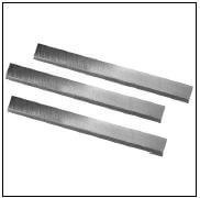
The following task is to let the learners get to know how to cut and grind cutting tools to enable them to work on a lathe machine. Material to be used is HSS steel bars. Learners are required to cut and grind two different cutting tools to be utilised on a lathe machine, namely;
- Right-hand cutting tool.
- Round nose cutting tool.
The same HSS steel bar can be utilised by utilising both ends of one bar in order to make it more affordable and saving material.
READ ALL THE INSTRUCTIONS FIRST - THEN PROCEED
FOLLOW ASSESSMENT INSTRUCTIONS - AS INDICATED
Resources Required:
- HSS 12 x 12 x 100 Square tool-bit bar

- Bench Grinder with rough and fine grinding stone.

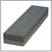
- Oil sharpening stone (to sharpen cutting tools).

- Marking medium (Engineers blue, Koki pen, chalk etc.)
- Marking off instruments (Square, scriber etc.)
- Appropriate Personal Protection Equipment (PPE).

ASSESSMENT TASK 1- Grade 10
PRACTICAL SKILLS TASK- Tool Grinding
Activity Outcome
- Learners familiarize themselves with the grinding and use of cutting tools for lathe machines.
- Learners apply theoretical knowledge in practice to grind and sharpen LATHE CUTTING TOOLS.
How to Grind Tool Bits
Use a bench grinder to sharpen your tool bits. Even an inexpensive bench grinder can do a good job grinding lathe tool bits. In some cases, you might want to purchase a higher quality fine grit wheel.
Keep a small cup of water near your grinder.
Grinding generates heat, which can cause two problems. The tool bit will become too hot to hold. Overheating can also affect the heat treatment of the tool bit, leaving the cutting edge soft.
Use a protractor to measure the angles. They are not super-critical, but you should try to stay within one degree of the recommendations.
Grind the Front Relief
The first step in creating a tool bit is to grind the front relief. For most work, a relief angle of 10° works well. While you are grinding the front relief, you are also creating the front cutting edge angle. Make this angle about 10° also, so that the corner formed by the front cutting edge and the side cutting edge is less than 90°.
Grind the Left Side Relief
Form the left side relief next. Again, create about a 10° angle. You don’t need to form a side cutting angle. The side cutting edge can be parallel to the side of the tool blank.
Grind the Top Rake
The top of the tool bit is ground at an angle that combines the back rake and the side rake. The side rake is most important, because the side cutting edge does most of the work. For cutting steel and aluminium, the side rake should be about 12° and the back rake should be about 8°. For cutting brass, the rake angles should be much less, or even 0°.
Round the Nose
A small nose radius allows you to turn into tight corners. A large nose radius produces better surface finishes. Create a nose radius that is appropriate for the tool bit you are creating.
PROCEDURE:
NB! Throughout this sequence the tool temperature was kept reasonable by frequent dipping in a pot of water. Also - always ensure that the safety guards are in place on the grinding wheel, and always wait for it to stop before adjusting the rest.
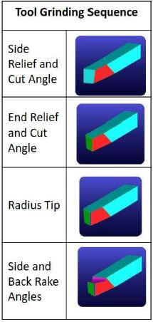
Task 1 A: Right angle cutting tool
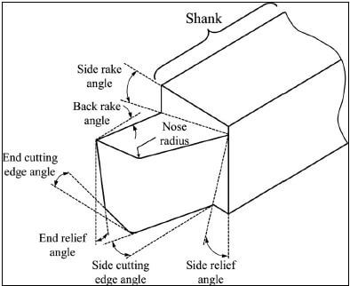
Figure 1.1. Tool Geometry 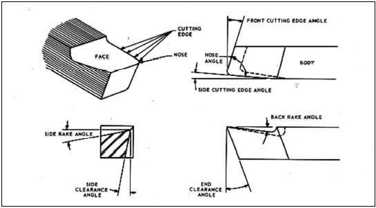
Figure 1.2 Tool cutting angles for Right Angled cutting tool
CLEARANCE ANGLES | ||||
Material | Side Relief | End Relief | Side Rake | Back Rake |
Aluminium | 12° | 8° | 16° | 35° |
Steel | 12° | 8° | 12°→18° | 8°→15° |
- Take the 12 x 12 x 100 HSS bar and start marking off the 1st angle to be grinded which is the Side Cutting angle.
- Use the table provided to measure the required angles for grinding your tool for the material to be used either for Steel or Aluminium.
- First grind the first side and the mark the second side and then only grind the second side.
- Use the following diagram to assist you in the sequence of grinding:

- During the grinding process, keep using water to cool down your project.
- When completed, use an oil sharpening tone in order to sharpen and finish your tool.
Task 1 B: Straight Round Nose cutting tool.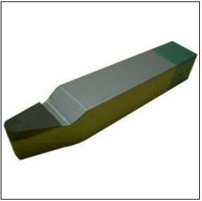
Figure 1.3. Completed Round Nose cutting tool 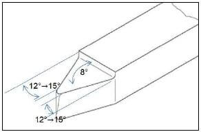
Figure 1.4. Round Nose grinding angles
- Take the same 12 x 12 x 100 HSS bar and start marking off the 1st angle to be grinded which is the Side Cutting angle.
- Grind the side angle to the appropriate angle and proceed to the second side and grind
- During grinding keep using continuously the water to cool the tool.
- After grinding both sides, grind the front rake angle.
- Proceed to grind the top rake angle.
- Use the oil sharpening stone to finish your tool and sharpening it.
Assessment of project 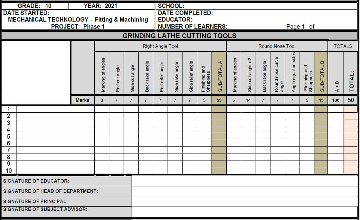
PHASE TWO:
Grade 10 Fitting & Machining
Terminology - Turning Task
Procedure
The following task is to let the learners get to know how to work with the lathe machine. Choice of material to be used is Aluminium or Nylon / Teflon.
READ ALL THE INSTRUCTIONS FIRST - THEN PROCEED
FOLLOW ASSESSMENT INSTRUCTIONS - AS INDICATED
Resources Required:
- Aluminium or Nylon/ Teflon Ø30mm rough cut at 150mm long.
- Centre lathe with related attachments and tools.
- Lathe cutting tools for facing, parallel turning, taper cutting and parting off.
- Vernier and other measuring equipment (callipers, steel rule etc).
- Marking medium (Engineers blue, Koki pen, chalk etc.)
- Marking off instruments (Square, scriber etc.)
- Appropriate Personal Protection Equipment (PPE).
ASSESSMENT TASK 2- Grade 10
PRACTICAL SKILLS TASK- Lathe Turning
Activity Outcome
- Learners familiarize themselves with the use of tools and machines.
- Learners apply theoretical knowledge in practice to make the PIN PUNCH.
Requirements:/Tools:
- Lathe machine
- Tool bit holder and key
- Tool facing and cutting parallel surfaces
- Chuck and Tailstock centre
- Two tool bits
- Vernier calliper
PROCEDURE:
Check the following:
- All automatic feeds are disengaged.
- No persons cleaning, oiling or repairing machine.
- Work piece clamped safely and securely in chuck.
- Chuck key removed from chuck.
- Cutting tool correctly ground.
- Check and set correct cutting speed.
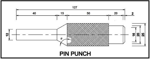
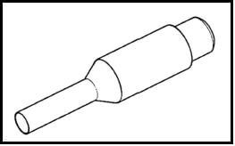
PROCEDURE IN MAKING THE PIN PUNCH.
- Cut a piece of material with length of 150mm long and of a 30mm diameter.
- Place work piece in the lathe chuck and tighten.
- Set up a facing cutting tool to the correct centre height.
- Move cutting tool away from lathe and work piece.
- Check that no automatic feed is engaged.
- Check the selected speed and apply feed for the material to be cut, adjust if necessary.
- Stand clear and switch the machine on.
- Move the cutting tool closer and final adjust with the compound slide to take the first cut.
- Take a second cut if needed.
- Cut material down to a diameter of 25mm. Tolerance must be within ±0,01
- Length must not be less than 127mm.
- Measure 40mm on one end and reduce to diameter 12mm.
- Calculate the correct angle the compound slide must be set to in order to cut a taper of a length of 15mm
- Set compound slide to the correct angle in order to cut the taper.
- Cut a taper to a length of 15 mm.
- Reduce on the 25mm side 20mm in length from back to a diameter of 20mm.
- Camphor 2mm at to a diameter of 16mm.
- Produce knurling on 50mm of the workpiece.
N.B. Use discretion for dimensions not given!
NOTE: Safety and Finishing (-5)
- A maximum of FIVE NEGATIVE marks allocated.
- Less 1 mark for vice (jaw) damage - clamping marks for overtightening or loose slip.
- Less 1 mark for lack of overall manufacturing competency in finishing / “look” of completed task related to surface finish, edges, square-ness, centrality, etc.
- Less 1 mark: Repetitive disregard for the use of PPE while working in the workshop.
- Less 1 mark: Another negative mark for continuing to have a disregard for the use of PPE while working in the workshop.
- Less 1 mark: Quality versus Time – “rush” job vs inefficient time to complete a good job.
Assessment of project
| CLASS: | YEAR: | SCHOOL: | |||||||||||||
| DATE STARTED: | DATE COMPLETED: | ||||||||||||||
| TEACHER: | NUMBER OF LEARNERS: | ||||||||||||||
|
Task 1A Pin Punch | FACETS | ||||||||||||||
| 1 | 2 | 3 | 4 | 5 | 6 | 7 | 8 | 9 | 10 | 11 | 12 | 13 | 14 | ||
| facing and centre drill | Ø 25mm | Ø 20mm | Ø 12mm | length 40mm of Ø 12 | length 50mm of Ø 25 | length 20mm of Ø 20 | taper length 15mm | calculation of taper | 45º chamfer 2 mm | knurling | finishing and safety | Total | Total | ||
| ## | Name of learners | 6 | 7 | 7 | 7 | 7 | 7 | 7 | 7 | 5 | 5 | 5 | 5 | 75 | 50 |
| 1 | |||||||||||||||
| 2 | |||||||||||||||
| 3 | |||||||||||||||
| 4 | |||||||||||||||
| 5 | |||||||||||||||
| 6 | |||||||||||||||
| 7 | |||||||||||||||
| 8 | |||||||||||||||
| 9 | |||||||||||||||
SIGNATURES:
................................................ ................................................ ................................................ ................................................
EDUCATOR HEAD OF DEPARTMENT PRINCIPAL SUBJECT
PHASE THREE:
Grade 10 Fitting & Machining
Joining Methods - Candle Holder Base Plate
Procedure:
Learners are to do the following Practical Assessment Task for drilling, tapping and joining two projects together by means of bolts.
READ ALL THE INSTRUCTIONS FIRST THEN PROCEED
FOLLOW ASSESSMENT INSTRUCTIONS AS INDICATED
Material needed:
- One 160 x 160 x 5mm aluminium or steel plate rough cut to about 65mm per side octagon.
- M6 steel tap set.
- M12 steel tap set.
- Drill chart for tapping.
- Drill sizes required for drill M6 and M12 tapping holes.
- Drill machine or drill press.
- Four M6 x 1,5 x 25mm bolts.
- One M12 x 1.75 x 25mm bolt.
- Vernier and other measuring equipment (callipers, steel rule etc).
- Marking medium (Engineers blue, Koki pen, chalk etc.)
- Marking off instruments (Square, scriber, straight edge etc.)
- Appropriate Personal Protection Equipment (PPE).
- 21mm ring spanner or socket and ratchet
- 10mm ring spanner or socket and ratchet
Instructions:
- Square the plate by using appropriate metal files, removing round edges and straightening the “rough cut” done by hacksaw or guillotine – reducing the workpiece to 155 x 155 x 5.
- Request a formal assessment on the square-ness of the plate before proceeding.
- Mark out the octagon sides measuring 65mm on each side.
- Mark out the centre points for the five holes on the flat bar / plate as indicated on drawing for the Candle Holder Base Plate.
- Centre punch these drill points to ensure that the drill remains in place when drilling.
- Request formal assessment on marking off and punch marks on plate before proceeding.
- Cut the sides so all sides are 65mm of the octagon
- On this 5mm base plate, drill the appropriate tapping size holes (as per “drill chart” information) to cut the four M6 internal threads followed by the one M12 internal thread in the centre of the base plate as follows.
- Clean any burs / roughness caused by the drilling procedure.
- Request a formal assessment on the drilling and cleaning procedure, on the plate before proceeding.
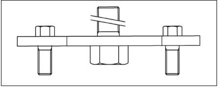
- Tap the base plate to fit the four M6 bolts and fit these from the top side of the plate, so that they form the legs.
(focus on cutting an even, square thread so that the base plate and legs will stand level) - Tap the base plate to fit the one centre M12 bolt and fit this from the bottom side of the plate, so that the candle holder that will be made in PAT FOUR, can be secured on this base plate with this M12 bolt.
(focus on cutting an even, square thread so that the candle holder will stand straight) - Request a formal assessment on the thread cutting and square-ness of the thread, on the plate before proceeding.
- Lock only THREE of the M6 bolts in place by tightening the bolt against the base plate.
(Do NOT use thread locking fluid, as the thread marking procedure can then not be moderated). - Hand the task in for moderation.
(Note the fourth “leg” does NOT get locked in place so that the thread can be moderated)
NOTE: Safety and Finishing (-5)
- A maximum of FIVE NEGATIVE marks allocated.
- Less 1 mark for vice (jaw) damage - clamping marks for overtightening or loose slip.
- Less 1 mark for lack of overall manufacturing competency in finishing / “look” of completed task related to surface finish, edges, square-ness, centrality, etc. • Less 1 mark: Repetitive disregard for the use of PPE while working in the workshop.
- Less 1 mark: Another negative mark for continuing to have a disregard for the use of PPE while working in the workshop.
- Less 1 mark: Quality versus Time – “rush” job vs inefficient time to complete a good job.
5mm Plate – Candle Holder Base Plate 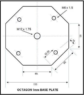
MARKING RUBRIC - PAT Phase 3 - Joining Task
| GRADE: 10 | YEAR: 2021 | SCHOOL: | ||||||||
| DATE STARTED: | DATE COMPLETED: | |||||||||
| MECHANICAL TECHNOLOGY | EDUCATOR: | |||||||||
| PROJECT: PAT PHASE 3 | NUMBER OF LEARNERS: | |||||||||
| Page 1 of ..... | ||||||||||
| BASE PLATE JOINING TASK | ||||||||||
| FACETS | Equal lenght of ALL 8 sides (65 × 65 × 65 × 65) | Octagon cut out neatly | Marking and Punching 2×5 | Drilling content size × 5 | Clean burs on all 5 holes | Tapping correctly | Threads/bolts turn squares to plates × 5 | Safety & finishing - negative marks for lack of safety and damage to task. | TOTAL | |
| Marks | 8 | 2 | 10 | 5 | 5 | 10 | 10 | -5 | 50 | |
| 1 | ||||||||||
| 2 | ||||||||||
| 3 | ||||||||||
| 4 | ||||||||||
| 5 | ||||||||||
| 6 | ||||||||||
| 7 | ||||||||||
| 8 | ||||||||||
| 9 | ||||||||||
| 10 | ||||||||||
| 11 | ||||||||||
| 12 | ||||||||||
| 13 | ||||||||||
| 14 | ||||||||||
| 15 | ||||||||||
| 16 | ||||||||||
| 17 | ||||||||||
SIGNATURE OF EDUCATOR: | ||||||||||
| SIGNATURE OF HEAD OF DEPARTMENT | ||||||||||
SIGNATURE OF PRINCIPAL: | ||||||||||
SIGNATURE OF SUBJECT ADVISOR: | ||||||||||
FINAL PAT TASK- PHASE 4
This task must be done during practical periods during Term 1 - 3.
Learners must adhere to safety rule and regulations during this task. Educator must demonstrate task to learners so that they can gain the confidence and necessary skills to complete this task.
The material needed for this task:
- 200mm long, Ø50 mm Aluminium rod.
- Cooling liquid for machines
- Suitable cutting tools on lathe machine
- Safety glasses
- Proper safety equipment
- Lathe machines
The lathe must be set up accordingly to the required speed for Ø50mm Aluminium.
Process:
- Face and centre drill both ends of the rod
- Parallel cut the work piece to a diameter of 43,5mm
- On the on end, parallel cut a step in the work piece to of Ø30mm and length of 20mm
- On the other end parallel cut a step in the work piece to a length of 32mm.
- Measure 15mm from the Ø30 end and cut two grooves of 3mm each with a spacing of 15mm in between, to a diameter of 38mm each.
- On a separate worksheet, calculate the degrees the compound must be set to in order for you to cut the taper.
- 5mm again from the grooves, cut the taper of 25mm long towards the front.
- On the 30mm long end, drill a Ø10,20 mm hole 20mm deep and tap to M12.
- On the Ø32 end, drill a Ø20 mm hole to depth of 30mm
- Take the base plate from Term 2 and fit the candle holder onto the base plate.
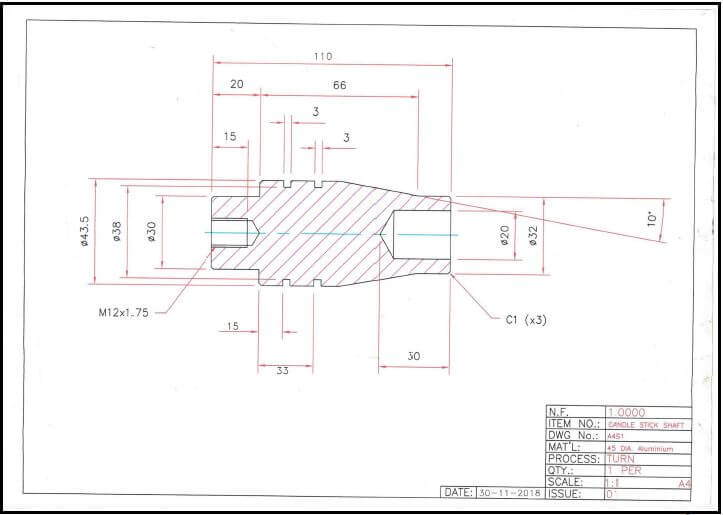
FINAL PAT Task – Grade 10
| GRADE: 10 | YEAR: 2021 | SCHOOL: | ||||||||||||||||||
| DATE STARTED: | DATE COMPLETED: | |||||||||||||||||||
| MECHANICAL TECHNOLOGY - Fitting & Machining | EDUCATOR: | |||||||||||||||||||
| PROJECT: FINAL PAT TASK - Turning | NUMBER OF LEARNERS: Page 1 of | |||||||||||||||||||
| TURNING TASK | ||||||||||||||||||||
| Diameter | Length | Taper | Drilling and fitting | |||||||||||||||||
| NAMES OF | FACETS | Facing and center drilling | 43,5mm diameter | 30mm diameter | Ø32mm in front of taper | 24mm length in front of taper | 2 × 1mm length | 2 × 3mm groove length | Ø30mm to a length of 20mm | 5mm length after groove | Taper calculations | 25mm length of taper calculations | Cutting taper | Drilling and tap M12 hole 20mm deep | Drill Ø20 hole 30mm deep | Fitment of base plate | Base plate square to holder | Time and safety | Finishing | TOTAL |
| MARKS | 6 | 6 | 6 | 6 | 6 | 6 | 6 | 4 | 6 | 8 | 5 | 5 | 5 | 5 | 5 | 5 | 5 | 5 | 100 | |
| 1 | ||||||||||||||||||||
| 2 | ||||||||||||||||||||
| 3 | ||||||||||||||||||||
| 4 | ||||||||||||||||||||
| 5 | ||||||||||||||||||||
| 6 | ||||||||||||||||||||
| 7 | ||||||||||||||||||||
| 8 | ||||||||||||||||||||
| 9 | ||||||||||||||||||||
| 10 | ||||||||||||||||||||
| 11 | ||||||||||||||||||||
SIGNATURE OF EDUCATOR: | ||||||||||||||||||||
| SIGNATURE OF HEAD OF DEPARTMENT: | ||||||||||||||||||||
SIGNATURE OF PRINCIPAL: | ||||||||||||||||||||
SIGNATURE OF SUBJECT ADVISOR: | ||||||||||||||||||||
ANNEXURE A
TOLERANCE | TURNING | FILING | MILLING flat surfaces | ||
| MARKS | Diameter | Length | Measure 4 places | Measure 4 places | |
| + 0.8 | + 0.8 | + 0.8 | + 0.8 | ||
| - 0.8 | - 0.8 | - 0.8 | - 0.8 | ||
| DEVIATION | 7 | 0,2 = 100% | 0,2 = 100% | 0,2 = 100% | 0,2 = 100% |
| 6 | 0,3 = 85% | 0,3 = 85% | 0,3 = 85% | 0,3 = 85% | |
| 5 | 0,4 = 70% | 0,4 = 70% | 0,4 = 70% | 0,4 = 70% | |
| 4 | 0,5 = 60% | 0,5 = 60% | 0,5 = 60% | 0,5 = 60% | |
| 3 | 0,6 = 40% | 0,6 = 40% | 0,6 = 40% | 0,6 = 40% | |
| 2 | 0,7 = 25% | 0,7 = 25% | 0,7 = 25% | 0,7 = 25% | |
| 1 | 0,8 = 10% | 0,8 = 10% | 0,8 = 10% | 0,8 = 10% | |
GRADE 10
PRACTICAL ASSESSMENT TASKS
PHASES ONE, TWO, THREE and FOUR
ANNEXURE B
DECLARATION OF AUTHENTICITY
NAME OF THE SCHOOL: …………………………………………………….……………………………………………….
NAME OF LEARNER: ………………………………………………………..………………………………………………. .
(FULL NAME(S) AND SURNAME)
EXAMINATION or I.D. NUMBER: …………………………………………………. NAME OF TEACHER: ……………………………………………………….
SCHOOL STAMP
|
I hereby declare that the project submitted for assessment is my own, original work and has not been previously submitted for moderation.
__________________________________________________ _______________________________
SIGNATURE OF CANDIDATE DATE
As far as I know, the above declaration by the candidate is true and I accept that the work offered is his or her own.
__________________________________________________ _______________________________
SIGNATURE OF TEACHER DATE