MECHANICAL TECHNOLOGY GRADE 12 MEMORANDUM - NSC PAST PAPERS AND MEMOS FEBRUARY/MARCH 2018
Share via Whatsapp Join our WhatsApp Group Join our Telegram GroupMECHANICAL TECHNOLOGY
GRADE 12
NSC PAST PAPERS AND MEMOS
FEBRUARY/MARCH 2018
MEMORANDUM
QUESTION 1: MULTIPLE-CHOICE QUESTIONS
1.1 C ✔ (1)
1.2 C ✔ (1)
1.3 B ✔ (1)
1.4 D ✔ (1)
1.5 C ✔ (1)
1.6 D ✔ (1)
1.7 A ✔ (1)
1.8 A ✔ (1)
1.9 A ✔ (1)
1.10 B ✔ (1)
1.11 A ✔ (1)
1.12 C ✔ (1)
1.13 B ✔ (1)
1.14 A ✔ (1)
1.15 D ✔ (1)
1.16 A ✔ (1)
1.17 C ✔ (1)
1.18 A ✔ (1)
1.19 B ✔ (1)
1.20 A ✔ (1) [20]
QUESTION 2: SAFETY
2.1 Spring tester
- Use correct attachments of the valve spring tester to compress the spring. ✔
- Do not exceed the prescribed pressure. ✔
- Ensure that the spring does not slip out. ✔
(ANY 2 x 1) (2)
2.2 Welding helmet
- To protect your eyes against the dangerous ultra-violet rays. ✔
- To protect your skin against the dangerous ultra-violet rays. ✔
- To protect your eyes against the sparks. ✔
- To protect your skin against the sparks. ✔
(ANY 1 x 1) (1)
2.3 Spot welding
- To prevent the electrodes from overheating. ✔ (1)
2.4 Testers
2.4.1 Brinell tester
- The tester must be mounted on the rigid spot on a workbench ✔
- The force must be applied at an angle of 90° to the test piece ✔
- Do not exceed the prescribed load ✔
- Make sure the test piece is placed securely into position ✔
(ANY 1 x 1) (1)
2.4.2 Tensile tester
- Make sure all safety guards are in place ✔
- Do not exceed the prescribed load ✔
- See that the test piece is securely placed in position ✔
- Make sure the dial indicator is mounted properly ✔
(ANY 1 x 1) (1)
2.4.3 Torsion tester
- Fasten the tester to the workbench ✔
- When you add pieces of different mass, you should attach them very gently otherwise you could get a skew reading of the torsion on the rod ✔
- Get specification (torsion) of the different materials and of the size rods you would like test ✔
(ANY 1 x 1) (1)
2.5 Bearing puller
- Perpendicular or 90° to the bearing. ✔ (1)
2.6 Cylinder leakage tester
2.6.1
- To prevent damage to the seals and tester ✔
- To ensure the correct reading ✔
(ANY 1 x 1) (1)
2.6.2
- To prevent damage to the tester and spark plug hole or injector hole ✔
- To ensure the correct reading ✔
(ANY 1 x 1) (1) [10]
QUESTION 3: TOOLS AND EQUIPMENT
3.1 Testers
3.1.1 Cylinder leakage tester
- Is used to determine a leakage in the cylinder✔.
- Determine the volume of leakage✔ (2)
3.1.2 Fuel pressure tester
- Is used to test the fuel operating pressure in the system ✔
- Is used to test the fuel pressure in the fuel line that runs to the direct injection. ✔ (2)
3.1.3 Torsion tester
- Is used to investigate the relationship between momentum or torque applied to material ✔
- Is used to investigate influence of material length on torsional deflection. ✔ (2)
3.2 Reasons for high CO2 reading
- Lean fuel mixture setting ✔
- Low compression ✔
- Faulty high tension leads ✔
(ANY 2 x 1) (2)
3.3 MIGS/MAGS-welding
3.3.1 Reasons for using inert gas during MIGS/MAGS welding
- Stabilises the arc on the parent metal ✔
- Shields the arc and weld pool from atmospheric gases like oxygen ✔ (2)
3.3.2 Advantages of MIGS/MAGS welding
- Can weld in any position ✔
- Less operator skill required ✔
- Continuous welding can be done ✔
- Causes less deformation ✔
- Faster than arc welding ✔
- Minimal post weld cleaning ✔
- No slag removal is required ✔
(ANY 2 x 1) (2) [12]
QUESTION 4: MATERIALS
4.1 Characteristics of structures
4.1.1 Austenite
- Soft ✔
- Coarse grain structure ✔
- Non-magnetic ✔
(ANY 2 x 1) (2)
4.1.2 Ferrite
- Soft ✔
- Ductile ✔
- Magnetic ✔
(ANY 2 x 1) (2)
4.2 Iron-carbon equilibrium diagram
4.2.1 Lower critical point (AC1) of steel
- The structure starts to change ✔✔ (2)
4.2.2 Higher critical point (AC3) of steel
- The structure turns into complete Austenite ✔✔
- The steel completely loses its magnetic properties ✔✔
- The structure turns into its finest grain size ✔✔
(ANY 1 x 2) (2)
4.3 Reasons to enhance properties of a crankshaft
- To produce a hard face with a tough core. ✔
- To induce toughness ✔ (2)
4.4 Reasons for the tempering of a camshaft
- To increase the lifespan of the camshaft ✔
- To eliminate brittleness caused by hardening. ✔
(ANY 2 x 1) (2)
4.5 Heat treatment process on piston rings
- Hardening ✔ (1) [13]
QUESTION 5: TERMONOLOGY
5.1 Key dimensions
5.1.1 The width of the key
- Width = D
4
= 120 ✔
4
= 30 mm ✔ (2)
5.1.2 The thickness of the key
- Thickness = D
6
= 120 ✔
6
= 20 mm ✔ (2)
5.1.3 The length of the key
- Length = D × 15 ✔
= 120 × 15 ✔
= 180 mm (2)
5.2 Indexing
- Indexing = 40
n
= 40 ÷ 2 ✔
124 2
= 20 ✔
62
No full turns and 20 holes in a 62 hole circle (3)
5.3 Height of screw the screw thread
- H = 0 866
= 3 × 0 866 ✔
= 2 6 mm ✔ (2)
5.4 Gear terminology
5.4.1 Addendum = m
- = 3 mm ✔ (1)
5.4.2 Dedendum
- = 1,157 m or =1,25 m
= 1,157 x 3 ✔ =1,25 x 3 ✔
= 3,47 mm ✔ =3,75 mm ✔ (2)
5.4.3 Clearance
- = 0,157 m or =0,25m
= 0,157 x 3 ✔ =0,25 x 3 ✔
= 0,47 mm ✔ =0,75 mm ✔ (2)
5.4.4
- Module = PCD
T
PCD = m × T ✔
= 3 × 48 ✔
= 144 mm ✔(2)
5.4.5
- OD = PCD + 2m ✔
= 144 + 2(3)
= 144 + 6
= 150 mm ✔ (2)
5.4.6 Cutting depth
- = 2,157 m ✔ or =2,25m ✔
= 2,157 x 3 =2,25 x 3
= 6,47 mm ✔ =6,75 mm ✔ (2)
5.4.7 Circular pitch
- = m x π✔
= 3 x π
= 9,42 mm ✔ (2)
5.5 Setting of the lathe and cutting tool to cut a metric V-screw thread:
- Set the lathe to the correct speed for screw cutting ✔
- Set the lead screw according to the required pitch ✔
- Set the dial gauge to position with the required worm gear ✔
- Set the compound slide to half the included angle of the thread (30°) ✔
- Set the cutting tool centre height and 90° to the work piece with the help of a centre gauge ✔
- Set cross slide and compound slide collars to zero with the tool touching the work piece ✔ (6) [30]
QUESTION 6: JOINING METHODS
6.1 Welding defects
6.1.1 Slag inclusion
- Welding speed too fast ✔
- Not removing the slag from the previous weld run before welding the next run ✔
- Current too low ✔
(ANY 2 x 1) (2)
6.1.2 Incomplete penetrations
- Welding speed too fast ✔
- Faulty joint design ✔
- Electrode too large ✔
- Current too low ✔
(ANY 2 x 1) (2)
6.2 Atmospheric contamination during MIGS/MAGS welding
- Inadequate shielding gas flow ✔
- Excessive shielding gas flow ✔
- Severely clogged nozzle ✔
- Damaged gas supply system ✔
- Excessive wind in the welding area ✔
(ANY 2 x 1) (2)
6.3 Nick break test
- Make a hacksaw cut at both edges, through the centre of the weld ✔
- Place the saw-nicked specimen on two steel supports ✔
- Use a sledge hammer to break the specimen by striking it in the zone where you made the saw cuts ✔
- Defects like incomplete fusion, slag inclusion and brittleness will be exposed in the break ✔
- Any defects bring it to the attention to the welder to rectify it ✔ (5)
6.4 Reasons for destructive tests
6.4.1 Bend test
- To determine the ductility/elongation ✔✔ of the weld metal. (2)
6.4.2 Machinability test
- To determine the welds hardness ✔ and its strength. ✔ (2)
6.5 X-ray test
- To detect internal defects in the weld metal✔✔ (2)
6.6 Weld crater
- Forms where welding is resumed at the bottom of the previous weld instead of on the top ✔✔ (2)
6.7 MIGS/MAGS welding
6.7.1 Welding process
- MIGS/MAGS welding ✔ (1)
6.7.2 Labelling
- A. Parent metal ✔
- B. Arc ✔
- C. Electrode wire ✔
- D. Gas shroud ✔
- E. Shielding gas ✔ (5) [25]
QUESTION 7: FORCES
7.1 Resultant 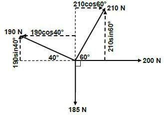
- ∑HC = 200 + 210cos60 - 190cos 40º ✔
= 200 + 105 - 145.55 ✔ ✔ ✔
= 159,45 N ✔ (4) - ∑VC = 210sin 60º + 190sin 40º - 185
= 181,87 + 122,13 - 185 ✔✔
= 119 N ✔ (3)
OR
Horizontal components | Magnitudes | Vertical components | Magnitudes |
200N | 200 N ✔ | 210NSin60º | 181,87N ✔ |
210N | 105 N ✔ | 190NSin40º | 122,13 N ✔ |
190N Cos40º | -145,45 N ✔ | -185 N | -185 N |
TOTAL | 159,45 N ✔ | TOTAL | 119 N ✔ |
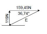
2 2 2
- E2 = HC2 + VC2
E = √ 159,452 + 1192
E = 198,96 N ✔ ✔ (3)
(3)
Tan θ = VC✔
HC
= 119
159,45N
= 36,74º E
E = 198,96N 36,73º south of west ✔
OR
= 36º 44' minutes south of west ✔ (3)
 (3)
(3) 7.2 Stress and Strain
7.2.1 Resistance area
- A = π (D2 - d2)
4
= π (0,0562 - 0,0382) ✔
4
= 1,33 × 10⁻³m2 ✔ (2)
7.2.2 Stress
- Stress = force
area
stress = 20 × 103
1,33 × 10-3
=15037593,98 Pa
Stress= 15,04MPa ✔(3)
7.2.3 Strain
- Strain = Δl ✔
OL
Strain = 50 - 49,975
50
Strain = 0,025
50
= 0,5 × 10⁻³ ✔ (3)
7.2.4 Young’s Modulus of Elasticity
- Youngs Modulus of Elasticity = Stress ✔
Strain
E = 15,04 × 10⁶
0,5 10-3
= 30,08 × 10⁹ Pa
= 30,08 GPa ✔ (3)
7.3 Moments
7.3 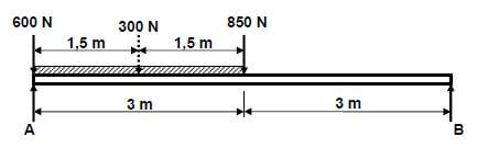
Calculate B. Moments about A:
- ∑LHM =∑ RHM
( B × 6) = (300 × 1,5) + (850 × 3) ✔
6B = 3000 ✔
6 6
B = 500N ✔
Calculate A. Moments about B:
- ∑RHM =∑LHM
(A × 6) =(850 × 3) +(300 × 4,5) + (600 × 6)
6A = 2550 + 1350 + 3600
6A = 7500 ✔
6 6
B = 1250N ✔(6) [30]
QUESTION 8: MAINTENANCE
8.1 Reason using SAE 20W50
- This to ensure that the oil is able to satisfy the operational ✔ requirements over a range of temperature ✔ from start-up to running hot. (2)
8.2 Maintain V-belt drive systems
- Check the contact surfaces of the pulley to prevent the belt from being damaged.✔
- Check the belt condition and replace if it is worn.✔
- Correct installation procedure must be followed. ✔
- Belt drives should be well guarded to prevent foreign objects to come into contact with the belts and pulleys.✔
- Keep guard mesh free of papers, rags, etc. that can cause insufficient air flow. ✔
- Check that the belt deflection is according to specification. ✔
- Store replacement belts in a cool, well ventilated place. ✔
- Correct alignment of pulleys. ✔
(ANY 2 x 1) (2)
8.3 Flash point
- It is the lowest temperature ✔ at which the oil gives off vapours ✔ which can ignite. ✔ (3)
8.4 Maintaining cutting fluid
- Avoid contamination of the cutting fluid by draining and regularly replacing it. ✔
- Always clean the machine's splash tray of metal cutting after use. ✔
- Regularly wipe cutting fluid splashes of machine parts. ✔
- Ensure that the sump is topped up from time to time and check that there is sufficient flow of cutting fluid to the cutting tool. ✔
(ANY 2 x 1) (2)
8.5 Functions of the clutch plate
- It provides friction between the flywheel and pressure plate. ✔
- It serves as a link between the clutch and the gearbox main shaft. ✔ (2)
8.6 Reasons for skimming the flywheel
- To remove the grooves caused by the clutch plate. ✔
- To ensure a full contact surface between the flywheel and the clutch plate. ✔
- To prolong the life of the clutch plate. ✔
(ANY 2 x 1) (2)
8.7 Properties of grease
- It must be water resistant, it must not mix with water ✔
- Prevents rust/corrosion ✔
- Good for load pressures ✔
- High melting point ✔
- Low freezing point ✔
- Prevent gumming ✔
- Be able to lubricate ✔
- High viscosity ✔
(ANY 2 x 1) (2) [15]
QUESTION 9: SYSTEMS AND CONTROL
9.1 Gear drives
9.1.1 Rotation frequency of input shaft
- NA = TB × TD × TF
NF TA × TC × TE
NA = TB × TD × TF × NF
TA × TC × TE
= 30 × 46 × 80 × 160
20 × 18 × 42
= 1401,90r/min (3)
9.1.2 Velocity ratio
- VR= NA
NF
VR= 1401,90
160
= 8,76: 1 ✔ (2)
9.2 Belt drives
9.2.1 Rotation frequency of driver pulley
- NDR × DDR = NDN × DDN
NDR = NDN × DND
DDR
= 733,33 × 0,36
0,24
= 200r/min (3)
9.2.2 Power transmitted
- P = (T1 - T2)πDn
60
P= (360 - 90)π × 0,36 × 733,33
60
= 3732,20 Watts
=3,73 kW (2)
9.2.3 Belt speed
- Belt speed = πDN
60
= π × 0,36 × 733,33
60
= 13,83m.s-1 ✔ (2)
9.3 Hydraulics
9.3.1 Fluid pressure
- AB = πD2
4
= π0,042
4
= 1,26 × 10⁻³m2 - PB = F
AB
= 275
1,26 × 10-3
= 218253,97 pa
or
= 218,25 kPa (5)
9.3.2 Diameter of piston B
- PB =PA
PB = FB
AB
AB = FB
PB
AB = 5,56 × 10³
218,25 × 10³
AB = 25,48 × 10⁻³m2
AB = πD2
4
DB = √AB × 4
π
= √25,48 × 10-3 × 4
π
=0,18 m
or
=180 mm (4)
9.4 ABS
- ABS prevents wheels from skidding ✔ when breaking hard ✔ in difficult conditions. (2)
9.5 ECU
- Electronic Control Unit ✔ (1)
9.6 Traction Control
- Prevent wheels from spinning. ✔
- Improves road holding ✔
(ANY 1 x 1) (1) [25]
QUESTION 10: TURBINES
10.1 Reaction turbines
- Francis ✔
- Kaplan ✔
- Tyson ✔
Gorlov ✔ (ANY 2 x 1) (2)
10.2 Supercharger boost
- Boost refers to the increase in intake manifold pressure ✔ that exceeds normal atmospheric pressure✔ (2)
10.3 Blowers
- Roots ✔
- Centrifugal ✔
- Vane-type ✔
- Twin screw type ✔
(ANY 2 x 1) (2)
10.4 Gas turbine
- A = Clean air inlet ✔
- B = Compression ✔
- C = Combustion ✔
- D = Exhaust ✔
- E = Turbine ✔
- F = Combustion chamber ✔ (6)
10.5 Application of a gas turbine
- Jet engines ✔
- Naval ships ✔
- Hi-performance vehicles and boats ✔
- Generating electricity ✔
(ANY 2 x 1) (2)
10.6 Advantages of a gas turbine
- Less complex than internal combustion piston engines ✔
- Only one moving part (Common shaft for: compressor and turbine) ✔
- Operate at higher revolutions per minute ✔ (ANY 2 x 1) (2)
10.7 Waste gate
- A waste gate is a valve that diverts exhaust gases away from the turbine wheel ✔ to regulate the turbine/compressor speed and boost.✔ (2)
10.8 Oil cooler
- To cool the oil ✔ that lubricates the turbocharger bearings and shaft. ✔ (2) [20]
TOTAL: 200