Tuesday, 22 June 2021 09:32

ELECTRICAL TECHNOLOGY: POWER SYSTEMS GRADE 12 - EXAMINATION GUIDELINES 2021

Share via Whatsapp Join our WhatsApp Group Join our Telegram Group

ELECTRICAL TECHNOLOGY:
POWER SYSTEMS
EXAMINATION GUIDELINES
GRADE 12
2021

TABLE OF CONTENTS  Page 
1. INTRODUCTION  3
2. ASSESSMENT IN GRADE 12   4
3. ELABORATION OF CONTENT FOR GRADE 12 (CAPS)  6
4. PREPARING LEARNERS FOR THE NSC: ELECTRICAL TECHNOLOGY  17
5. FORMULA SHEET: POWER SYSTEMS  22
6. CONCLUSION 23

1. INTRODUCTION
The Curriculum and Assessment Policy Statement (CAPS) for Electrical Technology: Digital outlines the nature and purpose of the subject Electrical Technology. This guides the philosophy underlying the teaching and assessment of the subject in Grade 12.
The purpose of these Examination Guidelines is to:

  • Provide clarity on the depth and scope of the content to be assessed in the Grade 12 National Senior Certificate (NSC) Examination in Electrical Technology.
  • Assist teachers to adequately prepare learners for the NSC examinations.

This document deals with the final Grade 12 external examinations. It does not deal in any depth with the School-based Assessment (SBA), Performance Assessment Tasks (PATs) or final external practical examinations as these are clarified in a separate PAT document which is updated annually.
These Examination Guidelines should be read in conjunction with:

  • The National Curriculum Statement (NCS) Curriculum and Assessment Policy Statement (CAPS): Electrical Technology
  • The National Protocol of Assessment: An addendum to the policy document, the National Senior Certificate: A qualification at Level 4 on the National Qualifications Framework (NQF), regarding the National Protocol for Assessment (Grades R–12)
  • The national policy pertaining to the programme and promotion requirements of the National Curriculum Statement, Grades R–12

2. ASSESSMENT IN GRADE 12

2. ASSESSMENT IN GRADE 12
2.1 Structure/Format of the question paper:

QUESTION  TOPIC  MARKS  TIME 
GENERIC – ALL   
 1 Multiple-choice Questions   15 14 min. 
 2 Occupational Health and Safety   10 9 min.  
GENERIC – ELECTRONICS AND POWER SYSTEMS
 3 RLC Circuits   35 32 min. 
SPECIFIC
4 Three-phase AC Generation 35 31min
5 Three-phase AC Generation 30 27 min.
6 Three-phase AC Generation 35 31min
7 Three-phase AC Generation 40 36min
TOTAL 200 180min

2.2 Cognitive levels

Bloom's Taxonomy consists of six levels, as shown below.
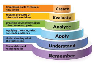
2.2

Related Items

DESCRIPTION OF COGNITIVE LEVEL  LEVEL  EXPLANATION  SKILLS DEMONSTRATED  ACTION VERBS  
 CREATING  4 The learner creates new ideas and information using the knowledge previously learned or at hand. At the extended abstract level, the learner makes connections, not only within the given subject area, but also beyond it and generalises and transfers the principles and ideas underlying the specific instance. The learner works with relationships and abstract ideas. 
  • Generating
  • Planning
  • Producing
  • Designing
  • Inventing
  • Devising
  • Making
devise, predict, invent, propose, construct, generate, make, develop, formulate, improve, plan, design, produce, forecast, compile, originate, imagine
EVALUATING   4 The learner makes decisions based on in-depth reflection, criticism and assessment. The learner works at the extended abstract level. 
  • Checking
  • Hypothesising
  • Critiquing
  • Experimenting
  • Judging
  • Testing
  • Detecting
  • Monitoring
 
combine, integrate, modify, rearrange, substitute, compare, prepare, generalise, rewrite, categorise, combine, compile, reconstruct, organise, justify, argue, prioritise, judge, rate, validate, reject, appraise, rank, decide, criticise 
ANALYSING  3 The learner appreciates the significance of the parts in relation to the whole. Various aspects of the knowledge become integrated, the learner shows a deeper understanding and the ability to break down a whole into its component parts. Elements embedded in a whole are identified and the relations among the elements are recognised.
  • Organising
  • Comparing
  • Deconstructing
  • Attributing
  • Outlining
  • Finding
  • Structuring
  • Integrating
 analyse, separate, order, explain, connect, classify, arrange, divide, compare, select, infer, break down, contrast, distinguish, draw, illustrate, identify, outline, point out, relate, question, appraise, argue, defend, debate, criticise, probe, examine, investigate, experiment
 APPLYING   2  The learner has the ability to use (or apply) knowledge and skills in other familiar situations and new situations.
  • Implementing
  • Carrying out
  • Using
  • Executing
apply, demonstrate, calculate, complete, illustrate, show, solve, examine, modify, relate, change, classify, experiment, discover, construct, manipulate, prepare, produce, draw, make, compile, compute, sequence, interpret 
UNDERSTANDING AND ROUTINE APPLICATIONS  The learner grasps the meaning of information by interpreting and translating what has been learned.
  • Exemplifying
  • Comparing
  • Explaining
  • Inferring
  • Classifying
summarise, describe, interpret, calculate, contrast, associate, distinguish, estimate, differentiate, discuss, extend, comprehend, convert, explain, give example, rewrite, infer, review, observe, give main idea
REMEMBERING  1 The learner is able to recall, remember and restate facts and other learned information.
  • Recognising
  • Listing
  • Describing
  • Identifying
  • Retrieving
  • Recalling
  • Naming
 
list, define, tell, describe, identify, show, know, label, collect, select, reproduce, match, recognise, examine, quote, name

BASIC SKILLS LINKED TO THE SUBJECT:
The following skills are measured in the question paper. Visibility of these skills gives an indication of the overall skills required in the subject:

  • Ability to follow instructions
  • Identifying labels/labelling/making drawings/diagrams/schematic representations
  • Plotting and interpretation of graphs/data
  • Working out and interpreting calculations ‚
  • Organising/Recording and categorising data
  • Extraction and/or manipulation and/or evaluation of data
  • Explaining functional operation of circuits and/or components

NOTE:

CALCULATIONS  WAVEFORMS/FLOWCHARTS/CIRCUITS 

Generally the criteria used for calculations are as follows:

  • Correct formula
  • Substitution of values
  • Simplifying of values
  • Answer and correct units

Waveforms will be assessed according to the following criteria:

  • Type of waveform (input/output)
  • Correct labelling
  • Correct plotting of values (correct values, proportional plotting)
  • Labelling and units on Y-axis
  • Labelling and units on X-axis
  • Phase relationship


3. ELABORATION OF CONTENT FOR GRADE 12 (CAPS)

TOPIC  PRESCRIBED CONTENT  MARKS 
Multiple-choice Covers all content   15
Occupational health and safety  OHS Act, 1993 (Act 85 of 1993)
  • Definitions
  • Purpose of the Act
  • General duties of employers to their employees
  • General duties of employers and self-employed persons to persons other than their employees
  • General duties of manufacturers and others regarding articles and substances for use at work
  • Duty to inform
  • General duties of employees at work
  • Duty not to interfere with, damage or misuse devices/items
  • Functions of health and safety representatives
  • Report to inspector regarding certain incidents
  • Victimisation forbidden
  • Offences, penalties and special orders of court

Safety Revision

  • Unsafe actions
  • Unsafe conditions
  • Dangerous practices
  • Risk analysis
  • Human rights in the workplace
  • Work ethics
  • Revision of emergency procedures (Grade 10)
 10
RLC circuits (generic)
  • Effect of alternating current on R, L and C components in series and parallel circuits.
  • Describe/Define/Explain the following concepts and terminologies of RLC series and parallel circuits in words (not formulae):
    • Impedance
    • Inductive reactance
    • Capacitive reactance
    • Power factor
    • Phase angle
    • True power,
    • Resonant frequency
    • Q-factor
    • Bandwidth
  • Calculating the following in RLC series and parallel circuits containing ONE resistor, ONE capacitor and ONE inductor:
    • Frequency
    • Inductance
    • Inductive reactance
    • Capacitance
    • Capacitive reactance
    • Impedance
    • True power
    • Power factor
    • Phase angle
    • Voltage drop
    • Total current
    • Capacitive current
    • Inductive current
    • Q-factor
    • Bandwidth
    • Resonant frequency
  • Drawing of the phasor and wave representation of RLC circuits
  • Applications of RLC circuits
  • Conditions of series and parallel resonant circuits
  • Drawing of phasor diagrams of series, parallel and resonant circuits
  • Drawing of the characteristics curve and phasor diagram of resonant circuits
  • Illustrate the effect of changing frequency in an RLC circuit toward resonance
  • Calculations
  • Series RLC circuits containing ONE resistor, ONE capacitor and ONE inductor
  • Parallel RLC circuits containing ONE resistor, ONE capacitor and ONE inductor
(35)
Three phase AC generation (specific)

Principle of three-phase AC generation

  • Distribution networks – (outline generation network to distribution network)
    • Generation
    • Transmission
    • Distribution
  • Advantages of three phase over single phase
  • Disadvantages of single phase over three phase
  • Waveform of single- and three-phase systems
    • Know how to draw a fully labelled waveform of a three-phase system
    • The labelling of a waveform should be according to universally adopted sequence which is R.Y.B
  • Phasor diagram of single- and three-phase systems
  • Phasor diagram of a single- and three-phase systems
    • Know how to draw a fully labelled phasor diagram for a threephase systems
    • Show phase angles.
    • Show the direction of rotation

Three Phase Systems (3ϕ)

  • Star connection and symbol
  • Delta connection and symbol
  • Delta vs. Star (Know difference between the two)
  • Schematic (sketch without indication of components)
  • Diagrammatic (sketch with components) representations of threephase systems.(overview of distribution network, power station to end users)
  • Only balanced loads

Power in Three-phase (3ɸ) Systems and Calculations

  • Describe/Define/Explain the following:
    • Active Power
    • Reactive Power
    • Apparent Power
  • Calculations
    • Active power (True power) P = √3 ×V× LIL × Cos θ
    • Reactive Power Q ( PR )= √3 × VL ×IL ×Sin θ
    • Apparent Power s (Papp) = √3 x Vx LL

NOTE: Know power formula as the formula sheet is the guide not all formulae are there. Manipulation of formulae is key to the calculations in this section

Introduction to Star and Delta Calculations
Star

  • Line voltage and current
    VL =  √3VPH and IL = IPH

Delta

  • Line voltage and current
    VL = VPH and IL = √3IPH
  • Losses
  • Efficiency
    η = output power x 100% or η = input - losses x 100% 
          input power                            input power

Importance of power factor correction for consumers and suppliers: No calculation

Only Application of Meters in Three Phase (3ϕ)

  • Wattmeter
  • kWh meter (Energy meter)
  • Power factor meter
  • Two- and three-wattmeter connection/method
  • Calculation of two- and three-wattmeter
  • Methods of connections
 (35)
Three-phase transformer (specific)

Introduction of three-phase transformers

  • Principle of operation and connections of three-phase transformers
  • Describe/Explain the principle of operation of three-phase transformer in the correct order of processes.
  • Connection of three-phase transformer
    • Delta/star
    • Star/star
    • Star/delta
    • Delta/delta
  • Concept, explanation and understanding of losses
  • Copper losses (IR2): Losses due to the resistance of the wire.
  • Iron losses (core losses): Heat losses occurring due to the hysteresis of the core and eddy current
    • Eddy current
    • Hysteresis losses
  • Conceptual meaning of losses
  • Sources of heat generation in a transformer
  • Factors contributing to heat
  • Three-phase transformers compared to single-phase transformers
    • Comparison of single-phase transformers and three-phase transformers
  • Application of delta/star connection transformers
  • Construction of transformers
    • Know the types of the transformer construction
    • The comparison between the types of transformers
  • Application of transformers
  • Know and understand the :
    • Application of a transformer
    • The main function of a transformer
  • Cooling
    • Understand the cooling methods
  • Safety
    • Know the importance of safety in the workshop when working with a transformer
  • Protection
    • Identify/Describe/Explain the use of the protection devices in transformers

Calculations (Balanced Loads only)

  • Know, understand and apply the formula to :
  • Calculate the:
    • Transformation ratio
    • Number of turns
    • Line and Phase current, voltage and power
  • Know how to manipulate the formula
  • Power factor
    • Define/Explain power factor
  • Power
    • Know the calculations of power
  • Load including losses and efficiency
    • Know how to describe/Explain losses in transformers
    • Calculate efficiency
30
Three-phase motors and starters (specific)

Introduction to Three-phase (3ϕ) Motors

  • Three-phase squirrel-cage induction motor
  • Know and Understand :
    • How to read and interpret the details on the name plate of the motor
    • The purpose of three phase squirrel-cage induction motor
    • Explain the function/use of starter to start the induction motor
  • Principle of operation
    • Explain and know the function of each parts of squirrel-cage motor
    • Describe/Explain the operation of three-phase squirrel-cage induction motor
    • Know how the rotating magnetic field is produced or created
  • Construction
    • Describe the construction of a squirrel-cage motor
    • Explain and know the function of each parts of squirrel-cage motor
  • Advantages
    • Know and understand the:
    • Advantages of three phase squirrel-cage induction motor compared to single-phase motor.
  • Applications
    • State where to use the induction motor
  • Calculations on slip, power and efficiency
  • Describe/Explain the conceptual meaning of the following:
    • Slip
    • Efficiency
    • Power
  • Know the calculation of :
  • Slip – revs per minute: S = ns - nr
  • Per unit slip: S = n- nr
                                 ns 
  • Percentage slip: S = ns - nr x 100%
                                        ns

NOTE: Know and understand all the formulae as the formula sheet is the guideline and not all formulae are there

Understand the:

  • Relationship of speed vs torque
  • How the maximum torque is determined
  • Characteristic curve of torque vs speed

Synchronous Speed

  • What is synchronous speed? Knowledge and understanding the:
    • Conceptual meaning of synchronous speed
    • The equation of calculating synchronous speed
  • Relationship between synchronous speed and generated power

Electrical and Mechanical Aspects of Three-phase (3ϕ) Motors

  • Fault-finding/Troubleshooting
  • Motor testing. Know and understand the
    • Insulation resistance test
    • Continuity test
    • Loose connection test
    • Bearing test
  • Commissioning. The process involved in preparing the motor and starter to be used by the operator
  • Understand the checklist for commissioning a new installed motor.

Understand the starting of an electrical induction motor

3Φ Direct-on-line Starter with Overload

  • Function of components on diagrams
    • Identifying the components from the given circuit diagram
    • Know the description of each components
    • Describe/Explain the function of the starter
  • Principle of operation
    • Describe/Explain the operation of direct-on-line motor starter
  • Diagram
    • Identifying the control circuit
    • Know how to draw the circuit diagram
  • Wiring on a panel
    • Understand the wiring and working of the panel
  • Calculation of the overload value and setting of the overload
    • Calculate the power at full load.

3Φ Forward and Reverse Starter with Overload

  • Function of components on diagrams
    • Know all the components and their description.
    • Know the function of each component in the starter circuit.
  • Principle of operation
    • Know and understand:
    • In chronological order describe/explain the 3Φ forward and reverse starter with overload
    • How the direction of rotation of three-phase motors can be reversed

Diagram

  • Identifying the control circuit
  • Know how to draw the circuit diagram

Wiring on a panel

  • Understand the wiring and working of the panel
  • Explain the direction of rotation of a three-phase motor
  • Calculation of the overload value and setting of the overload

3Φ Sequence Motor Control Starter with Overload (Without Timer)

  • Function of components on diagrams
  • Know all the components and their description
  • Know the function of each component

Principle of operation:

  • Describe/Explain the operation of 3Φ sequence motor control starter with overload

Diagram

  • Identifying the type of the control circuit
  • Know how to draw the circuit diagram

Wiring on a panel

3Φ Sequence Motor Control Starter with Overload (With Timer)

  • Function of components on diagrams
  • Know all the components and their description
  • Know the function of each component

Principle of operation

  • Describe/Explain the sequential operation of 3Φ sequence motor control starter with overload (with timer)

Diagram

  • Identifying the type of the control circuit
  • Know how to draw the circuit diagram

Wiring on a panel

3Φ Automatic Star Delta Starter with Overload

  • Function of components on diagrams
  • Know all the components and their description
  • Know the function of each component.

Principle of operation

  • In chronological order the operation of 3Φ automatic star delta starter with overload

Diagram

  • Identifying the control circuit
  • Know how to draw the circuit diagram

Wiring on a panel

  • Understand the wiring and working of the panel
  • Calculation of the overload value and setting of the overload
 
Programmable logic controllers (PLCs) (specific)

Introduction to the Programmable Logic Control Device

History of the PLC

  • Method used for automated control for industrial production and processes at the time before PLC where developed.
  • Disadvantages of using relays for automated control as compared to PLCs
  • Know and understand why the PLC's where developed

Hard wiring vs. Soft wiring, know and understand the:

  • Conceptual meaning of hard wiring and soft wiring
  • Advantage of soft wiring vs hard wiring
  • Disadvantage of hard wiring vs soft wiring
  • Conceptual meaning of each advantage and disadvantage of hard wiring and soft wiring
  • The programmed scan cycle of a PLC
  • Steps that a PLC undergo to complete one programmed scan cycle (input scan, process scan and output scan)
  • Sequential operation of the PLC
  • Safety measures to be considered during programming of the PLC

PLC Software and Devices
Difference between analogue and digital/discrete inputs

  • Know and understand the conceptual meaning of:
  • Analogue input
  • Digital input
  • Know the importance of converting:
  • Analogue input to digital input
  • Digital output into analogue output

Logic gates and truth tables of AND, OR, NAND, NOT, NOR inputs to a PLC (Digital) (Can this be removed)

  • Relate either the given logic gate symbol, the truth table and the ladder diagram to:
  • Truth table
  • Ladder logic diagram
  • Symbol

Input devices to PLC

  • Examples of:
    • Switches as input devices
      • Push button (N/O) and (N/C)
      • N/O and N/C contacts/switch

Sensors as input devices

  • Proximity sensor
  • Temperature sensor
  • Light sensor
  • Level sensor
  • Overload sensor

Know the application/use of each sensor as input devices to PLC:

  • Proximity
  • Temperature
  • Light
  • Level
  • Overload

Outputs on a PLC

  • Transistor/Relay
    • Operation of transistor/relays
  • Contactors/relays:
    • Operation of contactors/relays (revision)
    • Correct symbols as used in:
      • Hard wiring and
      • Soft wiring circuit
  • Timers:
    • The purpose of timers as used in the operation of a PLC's logic circuit
    • Explaining/describing the following:
      • On delay timer contact
      • Off delay timer contact
  • Know when each timer contact is applied to the PLC logic circuit
  • Know and use the symbols of on delay and off delay timer contact in the PLC's logic circuit
  • Explain/Describe the sequential operation of the ladder logic diagram with timer function

Latching concepts (retaining circuits):

  • Identification of the 'latching/retaining' circuit in a control circuit
  • Understanding the use/function of the latching circuit

Interlocking:

  • Conceptual meaning of interlocking as used in the control circuit
  • Correct symbols used for interlocking

Markers/Flags (Memory elements): Purpose of markers as used in the ladder logic diagram

  • Conversion of hard-wired schematics (Control circuits) to ladder logic and labelling of symbols (motor starters only)
    • Identify the type of the control circuit to be converted
    • Know how to draw:
      • The power rails of the ladder logic diagram
      • Rungs with input and outputs between the power rails of the ladder logic diagram
    • Know the function of each components as in the control circuits
    • Know the sequence in which ladder logic operate

NOTE: Use the Engineering Graphics and Design (EGD) approach and not crude freehand drawings and that ladder logic circuit is drawn from left to right and operate from top to bottom.
Applications of PLCs: The PLC as a motor starter

  • The variable speed drive (VSD) as a programmable motor controller (concepts only)
  • Know and understand the function of VSD as used in motors
  • Explain/describe the positive effect of applying VSD in motors

Basic principle of operation

  • Input to VSD,
  • Output of VSD to the motor
  • Relationship between the speed of an AC motor and the frequency supplied to the motor
  • Introduction to VSD, know and understand the following:
    • Part (sections) of the VSD, namely:
      • Rectifier circuit
      • Filter circuit
      • Inverting circuit
        • Understand how the switches functions
        • Understand the effect the switching time has on the output waveform and the frequency
    • Function of each part
    • Sequential operation of the VSD
  • Methods of speed control
    • The V/Hz
    • Vector drives
    • Conception understanding of V/Hz and vector drive
  • Basic block diagram
  • Types of motors used with a VSD
    • Know the types of motors used with a VSD and where they are used.
  • Regenerative braking
    • Conceptual understanding of the term regenerative breaking
    • Understand the conversion from one form of energy to another during the braking process
    • Conceptual understanding of the term regenerative energy
    • Purpose of the braking resistor as used in the motor control circuit
    • Examples of regenerative braking
    • Know and understand the diagram showing how regenerative braking is applied to a motor control circuit
  • Basic applications of VSD
    • Application of VSD
    • Safety aspects to consider in the application of VSD
  • Start-up and run profiles (with applications) (programming – optional)
    • Characteristics curve of speed vs torque
    • Understand the relationship between speed and torque
    • Know and understand the speed range of (e.g. breakdown speed)
    • Characteristics curve of current vs torque
    • Understand the relationship between current and torque 
 (40)
  TOTAL 200

4. PREPARING LEARNERS FOR THE NSC: ELECTRICAL TECHNOLOGY
Learners do not intuitively know how to answer a question paper successfully. Teachers need to prepare learners to have the skills needed to negotiate a question paper successfully.
This preparation process starts in Grade 10 and culminates in Grade 12. Learners need to be coached in some of the following skills, which will help them in answering the question paper effectively:
Manipulation of formulae: The learners must learn how to use the standard formula, manipulate the formula correctly, correctly substitute values and remember to always add a value/unit with an answer.
Prefixes and units: Learners must have a clear understanding of the conversion and uses of units and abbreviations, such as kilo, milli, micro, nano, etc. Teachers should drill leaners on this skill.
Learners must be taught on how to approach a question paper and ANSWER BOOK.
Planning the answers: Learners must know how to answer in a chronological order of sequence and know how much space should be taken up by a typical answer. Do not break questions up and answer it haphazardly out of order. Ensure the numbering convention in the question paper is followed in the ANSWER BOOK.
Open spaces in the ANSWER BOOK: Teachers should encourage learners to answer ALL questions, including subquestions, and not leaving open spaces. Even when learners are unsure of the expected response, they are urged to answer to the best of their ability. This may lead their train of thoughts in the correct direction leading the learner to a correct or partially correct answer. Where learners leave an open space to proceed with the question paper, they should be taught to return to that space when the rest of the question paper is completed.
Teachers are urged to pay attention to Bloom's Taxonomy and should prepare learners to answer basic recall questions as well as more complex and intricate sentence-type questions, e.g. the paragraph- type answers such as the operation of a transformer.
Learners should be coached to regularly read questions and answers to homework and tests aloud in the class.
Teachers must encourage learners to engage in intelligent debate and discussion around subject content and on how an answer should be constructed. Learners must know how to structure their sentences in order to communicate what they are trying to say.
Learners must learn how to list facts. Answers are assessed on the principle of a single mark for a single fact.
Teachers must show the learners the difference between a sketch, a symbol and what a block diagram represents.
Below is an example of a sketch. It was drawn freehand and is a resemblance of a real-world device. Marks are awarded for drawings WITH LABELS. A drawing cannot be assessed without labels.
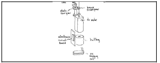
figure 1
FIGURE 1: SKETCH

Symbols: Symbols are simple representations of electronic devices and relates to the theory of how the device works and not necessarily to the appearance of the device. Without labelling and a title, it cannot be marked effectively.
symbols
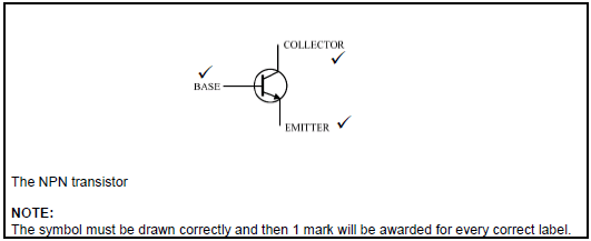
FIGURE 2: SYMBOL AND HOW IT IS MARKED

Block diagrams: Block diagrams are used extensively in Electrical Technology. It usually relates to processes and how devices operate. They are representative of the operation of a system/device and may not contain any physical resemblance to the device. Note that block diagrams may be given semi-complete, requiring the learner to fill or complete the other sections.
block
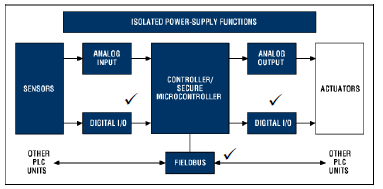
FIGURE 3: BLOCK DIAGRAM

All sketches, symbols, diagrams and waveforms must always be labelled and have a caption.
Learners must be shown how to interpret and use waveforms to support their answers.
Ladder logic: Ladder logic diagrams must be labelled and have each of the operands identified.
figure 4
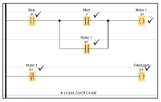
FIGURE 4: LADDER LOGIC

Sketches, diagrams and waveforms should be clear, not too small and easily interpretable.
Guard against small and illegible drawings.
Circuit diagrams: Circuit diagrams are marked on the following premise:

  • The circuit or portion of the circuit must be correct.
  • All components must have labels.
  • Note that whole circuits or portions of a circuit may be given and interrogated.

figure 5
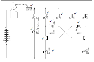
FIGURE 5: CIRCUIT DIAGRAM

Calculations:
Calculations should be done showing ALL steps.
Values must be placed correctly.
Units allocated to the calculation must be shown.
Wrong units will result in the answer being marked wrong.
No units will result in the answer being marked wrong.
It is good practice to draw a line underneath the final answer ending it in a small arrow. This indicates that the calculation is done.
figure 6
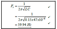
FIGURE 6: A CALCULATION AND HOW TO MARK IT

Lines must be drawn between questions.
Rough work should be labelled as rough work and have a line drawn through it.
Power factor (Cosθ): When using the power factor, learners should note whether they are given the power factor or the phase angle. Learners use the power factor as an angle, resulting in their answers being incorrect.
Phasor diagrams should always include an arrow showing its direction of rotation. As a phasor is a rotating vector and always rotates anticlockwise, it is required of learners to show this when doing graphical representations of phasors.
figure 7
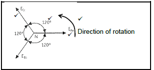
FIGURE 7: PHASOR DIAGRAM

Input and output waveforms: It is common in Electrical Technology to enquire from the learner what the result of an input waveform in a circuit may have on the output of the circuit. This is because the principle of input, process, output forms the cornerstone of how electric and electronic circuits operate.
By placing input and output waveforms directly underneath each other, in a synchronised fashion, the manner in which a circuit will affect a waveform is easily illustrated. The same applies to digital circuits.
figure 8
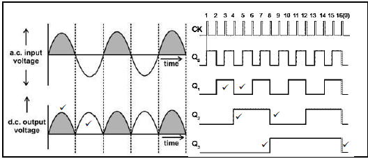
FIGURE 8: INPUT AND OUTPUT WAVEFORMS

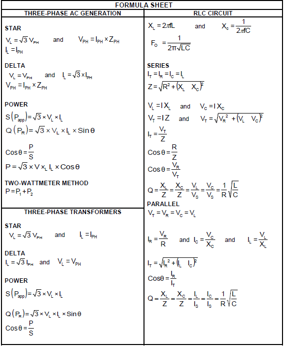
5. FORMULA SHEET: DIGITAL ELECTRONICS
NOTE: This formula sheet is only a guide and may not contain ALL the formulae as in the prescribed textbook and/or CAPS policy document.

formula sheet 1
6. CONCLUSION
It is envisaged that these Examination Guidelines will serve as an instrument to strengthen and empower teachers to set valid and reliable assessment items in all their classroom activities.
This Examination Guidelines document is meant to articulate the assessment aspirations espoused in the CAPS document. It is therefore not a substitute for the CAPS document which teachers should teach to.
Qualitative curriculum coverage as enunciated in the CAPS cannot be over-emphasised.

Last modified on Tuesday, 22 June 2021 11:17