MECHANICAL TECHNOLOGY GRADE 12 QUESTIONS - NSC PAST PAPERS AND MEMOS SEPTEMBER 2016
Share via Whatsapp Join our WhatsApp Group Join our Telegram GroupMECHANICAL TECHNOLOGY
GRADE 12
NATIONAL SENIOR CERTIFICATE
SEPTEMBER 2016
INSTRUCTIONS AND INFORMATION.
- Write your centre number and examination number in the spaces provided on the ANSWER BOOK.
- Read ALL the questions carefully.
- Answer ALL the questions.
- Number the questions correctly according to the numbering system used in this question paper.
- Start EACH question on a NEW page.
- Show ALL calculations and units. Round off final answers to TWO decimal places.
- Candidates may use non-programmable scientific calculators and drawing instruments.
- Take the value of gravitational force as 10 m/s2.
- All dimensions are in millimetres, unless stated otherwise in the question.
- A formulae sheet for your use is attached at the back of this question paper
- Use the criteria below to assist you in managing your time.
| QUESTION | CONTENT COVERED | MARKS | TIME (MINUTES) |
| 1 | Multiple-choice | 20 | 15 minutes |
| 2 | Safety | 10 | 10 minutes |
| 3 | Tools and equipment | 12 | 10 minutes |
| 4 | Materials | 13 | 10 minutes |
| 5 | Terminology | 30 | 20 minutes |
| 6 | Joining methods | 25 | 25 minutes |
| 7 | Forces | 30 | 30 minutes |
| 8 | Maintenance | 15 | 15 minutes |
| 9 | Systems and control | 25 | 25 minutes |
| 10 | Turbines | 20 | 20 minutes |
| TOTAL | 200 | 180 minutes |
QUESTION 1: MULTIPLE-CHOICE QUESTIONS
Various options are provided as possible answers to the following questions. Choose the answer and write only the letter (A–D) next to the question number (1.1–1.20) in the ANSWER BOOK, for example 1.21 D
1.1 Which ONE of the following safety procedures is applicable to the cylinder leakage test?
- Screw the adapter into the plug hole.
- Do not exceed the prescribed pressure in the cylinder.
- Place the spring on top of the tester.
- Make certain the dipstick is in the hole. (1)
1.2 Which of the following safety measures apply to a torsion tester?
- Fasten the tester to a workbench.
- Be careful of metal particles coming off after the metal fractures.
- Determine the strength of the bolts keeping the framework together.
- All the abovementioned. (1)
1.3 What safety measure is applicable to shears and guillotines in terms of workshop practices?
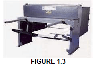
- Use the guillotine as a work bench.
- Guards should be removed when cutting metals.
- Do not use gloves when handling plates.
- Choose the correct blade for the job. (1)
1.4 Which of the following equipment is used to test the properties of electrical components?
- Brinell tester
- Rockwell tester
- Multimeter
- Terminal tester (1)
1.5 A beam bending tester is used to determine the … of various given pieces of material.
- distortion
- description
- deflection
- deterioration (1)
1.6 Cementite is also known as …, a compound of iron and carbon.
- metal carbide
- steel carbide
- iron carbide
- All the above mentioned (1)
1.7 What is the correct heat treatment temperature for piston rings?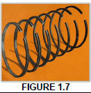
- 380 °C - 420 °C
- 480 °C - 520 °C
- 580 °C - 620 °C
- 680 °C - 720 °C (1)
1.8 Determine the width of a keyway to be used on a 100 mm shaft.
- 20 mm
- 35 mm
- 40 mm
- 25 mm (1)
1.9 Which engine part below can be machined with a face milling cutter?
- Crankshaft
- Cylinder head
- Connecting rod
- Camshaft (1)
1.10 What is the reason for applying the Nick-bend test on a welded joint?
- To determine the percentage of elongation of the weld metal
- To test the skill of the welder
- To check the magnitude of the weld
- To approve welds and welders to certain standards (1)
1.11 What is the reason for using visual examination in testing of welds?
- To train welders
- To check for size of the weld
- To test the welder
- To test the strength of the weld (1)
1.12 Identify a single force that can be representing the entire system of forces as shown in the diagram below.
- Polygon
- Equilibrium
- Equilibrant of forces
- Resultant (1)
1.13 Determine the compressive stress in a 20 x 20 mm square bar if it is subjected to a compressive load of 10 kN.
- 25 MPa
- 2,5 MPa
- 0,25 MPa
- 0,025 MPa (1)
1.14 Which ONE of the following is NOT a function of lubricating oil?
- It must prolong the engine life.
- It must increase the engine speed.
- It must reduce engine noise.
- It must act as a seal. (1)
1.15What is the ‘W’ known as in the classification of the SAE 20W50 oil?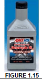
- ‘Winner grades’
- ‘Winter grades’
- ‘Wheel grades’
- ‘Wheel bearing’ (1)
1.16 The gear ratio of the compound gear in FIGURE 1.16 is …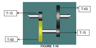
- 1 : 16
- 1 : 4
- 16 : 1
- 4 : 1 (1)
1.17 What is the name of the pulleys with the attached rope or chain known as in the FIGURE 1.17 below?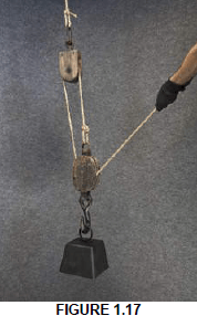
- Pulley and idler
- Wheel and axle
- Block and tackle
- Open belt pulley system (1)
1.18 What do we call the braking system used on the bike in FIGURE 1.18 below?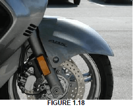
- Air brake system
- Ignition system
- ABC Braking system
- ABS braking system (1)
1.19 A supercharger is driven by …
- steam.
- exhaust gasses.
- mechanical drive.
- inlet gasses. (1)
1.20 Identify the water turbine in FIGURE 1.20: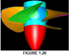
- Francis
- Tyson
- Kaplan
- Gorlov (1)
[20]
QUESTION 2: SAFETY
2.1
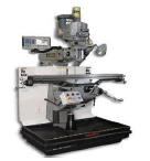
FIGURE 2.1
State TWO safety measures to be observed while the milling machine as in FIGURE 2.1 is in operation. (2)
2.2
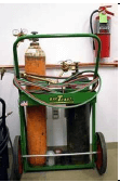
FIGURE 2.2
List TWO safety precautions that should be followed when using the oxy-acetylene apparatus in FIGURE 2.2. (2)
2.3 Name THREE safety rules when using the beam bending tester. (3)
2.4 State THREE common measures to be observed when using the Metal Arc gas-shielded welding (CO2 and Argon). (3)
[10]
QUESTION 3: TOOLS AND EQUIPMENT
3.1
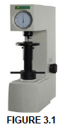
Explain the principle of the Rockwell Hardness test method. (4)
3.2 State TWO functions of the cooling tester. (2)
3.3 Describe the purpose of the following tests below.
3.3.1 Fuel pressure test (2)
3.3.2 Multimeter (2)
3.4
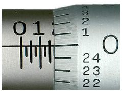
FIGURE 3.4
What is the reading on the micrometer as shown in FIGURE 3.4 above? (2)
[12]
QUESTION 4: MATERIALS
4.1 Describe each of the iron-carbon equilibrium diagram structures below.
4.1.1 Perlite (2)
4.1.2 Carbon content (2)
4.1.3 Martensite (2)
4.2 Which TWO methods are used for controlling material properties? (2)
4.3 What is the purpose of heat treatment? (2)
4.4 Describe in your own words what an iron-carbon diagram is. (2)
4.5 What is cementite also known as? (1)
[13]
QUESTION 5: TERMINOLOGY
5.1 With the aid of a sketch, show how you would centralise a cutter on a milling machine to cut a keyway on a round shaft. (6)
5.2 Explain the TWO milling processes below.
5.2.1 Conventional milling (2)
5.2.2 Climb milling (2)
5.3 A machinist has to turn a gear with 43 teeth on a milling machine. Calculate the indexing required completing the job. (4)
5.4 List the FOUR general screw thread fit classes and give a brief explanation of each. (8)
5.5
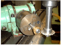
FIGURE 5.5
IDENTIFY and NAME the cutting procedure in FIGURE 5.5 above. (2)
5.6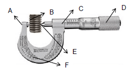
FIGURE 5.6
FIGURE 5.6 shows a screw-thread micrometer. Write down the letters in your ANSWER BOOK and the correct names of the parts next to the corresponding letters. (6)
[30]
QUESTION 6: JOINING METHODS
6.1 When mild steel is welded, numerous errors occur. Identify ONE possible defect and ONE preventive method when:
6.1.1 Atmospheric contamination is a cause. (2)
6.1.2 The weld bead does not penetrate the entire thickness of the base plate. (2)
6.1.3 Non-metallic solids are entrapped in the weld. (2)
6.2 Name THREE destructive tests exerted onto metals. (3)
6.3 Identify SIX basic components of the MIG welding machine. (6)
6.4
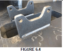
Describe how you would apply a Nick break test on a fillet weld. (6)
6.5
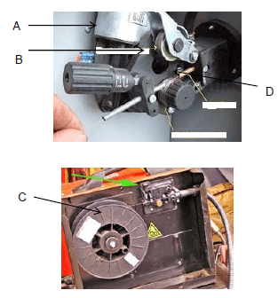
FIGURE 6.5
Label the MIG welding machine in FIGURE 6.5 above. (4)
[25]
QUESTION 7: FORCES
7.1 A load of 40 kN causes a tensile stress of 8 MPa in a mild steel round bar. The original length of the bar is 275 mm and Young’s Modulus for mild steel is 60 GPa.
Calculate the following:
7.1.1 The diameter of the mild steel bar (6)
7.1.2 The strain caused by the load (3)
7.1.3 The change in length caused by the load (3)
7.2 A hydraulic jack is being used to lift a vehicle with a mass of 35 kN. The maximum force that can be exerted onto the 34 mm plunger is 320 N.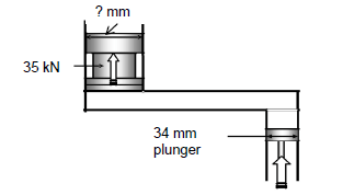
FIGURE7.2
Calculate the following:
7.2.1 The fluid pressure in the hydraulic system (3)
7.2.2 The diameter of the ram (4)
7.3 A beam of 10 mm rests on TWO supports. The ONE support is at the left end and the other support is 8 m from the left end. The beam carries a uniformly distributed load of 2 N/m between the supports.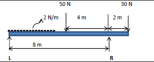
FIGURE 7.3
The beam also carries the following concentrated loads: 50 N 4 m from the left end; 30 N on the right end. Calculate the reaction at the supports. (6)
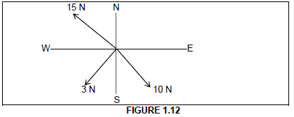
7.4
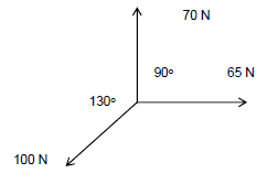
FIGURE 7.4
Calculate the magnitude and direction of the resultant force (R) in the system of forces above. (5)
[30]
QUESTION 8: MAINTENANCE
8.1
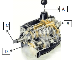
FIGURE 8.1
Identify the labels in the manual transmission in FIGURE 8.1 above. (4)
8.2 Why is it important for engine oil to have a high flashpoint? (2)
8.3

FIGURE 8.3
Explain the use of cutting fluid as applied in FIGURE 8.3 above. (3)
8.4
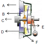
FIGURE 8.4
Write down the letters A–F of the mechanical clutch assembly IN YOUR ANSWER BOOK and then the correct labels for FIGURE 8.4 next to the corresponding letters. (6)
[15]
QUESTION 9: SYSTEMS AND CONTROL
9.1 FIGURE 9.1 below shows a gear drive system. Driver gear A has 16 teeth and meshes with gear B with 32 teeth on a countershaft. On this countershaft is another driver gear C with 14 teeth that meshes with gear D with 42 teeth on the output shaft.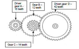
FIGURE 9.1
Determine by means of calculations:
9.1.1 The rotational frequency of the output shaft, if the input shaft rotates at 1330 r/min (revolutions per minute) (3)
9.1.2 The velocity ratio between the input shaft and the output shaft (2)
9.2 In a hydraulic press, a force of 400 N is applied to Piston A. Piston A moves 30 mm downwards. The diameter of Piston B is 145 mm and moves up by 14 mm.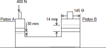
FIGURE 9.2
Make use of the specification in FIGURE 9.2 to calculate the following:
9.2.1 The fluid pressure in the hydraulic system (3)
9.2.2 The load that can be lifted (2)
9.3 FIGURE 9.3 shows a belt-drive system. A pulley with a diameter of 40 mm drives a driven pulley with a diameter of 120 mm. The driver pulley rotates at 100r/min.
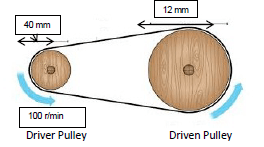
FIGURE 9.3
9.3.1 The rotational frequency of the driven pulley in r/min (2)
9.3.2 The power transmitted (2)
9.3.3 The belt speed of the system in meters per second (2)
9.4 An acetylene gas cylinder has a pressure and volume of 300 kPa (kN/m²) and 0,35 m³ respectively. The gas is being expanded until a new volume of 0,9 m³ is reached while the temperature remains constant. What will the new pressure be? (4)
9.5 Briefly explain the purpose of air bags in motor vehicle. (5)
[25]
QUESTION 10: TURBINES
10.1 Study the turbine in FIGURE10.1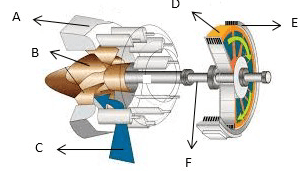
FIGURE 10.1
Label the letters A to F in your ANSWER BOOK. (6)
10.2 In which TWO groups are water turbines divided into? (2)
10.3 Explain the operation of a gas turbine with the Brayton cycle. (4)
10.4 Name FOUR advantages of a steam turbine. (4)
10.5 Name FOUR advantages of a gas turbine. (4)
[20]
TOTAL: 200
FORMULA SHEET
1. BELT DRIVES
1.1 Belt speed = πDN
60
1.2 Belt speed = π( D+t) x N (t = belt thickness)
60
1.3 Belt mass = Area x Length x Density (A = thickness width)
1.4 Speed ratio = Diameter of driven pulley
Diameter of driven pulley
1.5 Belt length (Flat) = [(D + d) x 1,57 ] + (2 x centre distance)
1.6 Open-belt length = π(D + d) + (D - d)2 +2cc
2 4c
1.7Crossed-belt length = π(D+d ) + (D + d)2 + 2c
2 4c
1.8 Power (P) =2πNT
60
1.9 Ratio of tight side to slack side =T1
T2
1.10 Power (P) = ( T1-T2) πDN where T1 = force in the tight side
60
1.11 Width = T1
Permissible tnsile force
1.12 Torque = Force x radius
2. STRESS AND STRAIN
2.1 Stress = Force or (σ = F)
Area A
2.2 Strain = Change in length
Original Length
2.3 Young’s modulus (E) = Stress of (σ)
Strain ε
3. HYDRAULICS
3.1 Pressure (P) = Force (F)
Area (A)
3.2 Volume = Cross sectional area x stroke length (l or s)
3.3 Work done = Force x Distance
3.4 P1 x V1 = P2 x V2
4. GEAR DRIVES
4.1Power (P) =2πNT
60
4.2 Gear ratio = Number of teeth on driven gear
Number of teeth on driven gear
4.3 Torque = Force x radius
4.4 Torque transmitted = gear ratio x input torque
4.5 Module (m) = Pitch - circle diameter (PCD)
Number of teeth (T)
4.6 Pitch-circle diameter (PCD) = Circular Pitch (cp) x number of teeth (T)
π
4.7 Outside diameter (OD) = PCD + 2 module
4.8 Addendum (a) = module (m)
4.9 Dedendum (b) = 1,157 m or Dedendum (b) = 1, 25 m
4.10 Cutting depth (h) = 2, 157 m or Cutting depth (h) = 2,25 m
4.11 Clearance (c) = 0,157 m or Clearance (c) = 0,25 m
4.12 Clearance pitch (CP) = m X π
5. PULLEY DRIVES
5.1 N1D1 = N2D2
5.2 Power (P) =2πNT
60
5.3 Velocity Ratio =Diameter of driven pulley
Diameter of driven pulley
5.4 r/min of driving pulley = r/min of driver x diameter of driven pulley
diameter of driven pulley
6. KEYS
6.1 Width of key = Diameter of shaft
4
6.2 Thickness of key = Diameter of shaft
6
6.3 Length of key = 1,5 x diameter of shaft
6.4 Standard taper of key : 1 in 100 or 1 : 100
7. CINCINNATI DIVIVIDING HEAD TABLE FOR MILLING MACHINE
7.1
| Hole circles | |||||||||||
| Side 1 | 24 | 25 | 28 | 30 | 34 | 37 | 38 | 39 | 41 | 42 | 43 |
| Side 2 | 46 | 47 | 49 | 51 | 53 | 54 | 57 | 58 | 59 | 62 | 66 |
7.2
| Standard change gears | ||||||||||
| 24 x 2 | 28 | 32 | 40 | 44 | 48 | 56 | 64 | 72 | 86 | 100 |
Indexing formula = 40 (Where N = Number of divisions)
N