ELECTRIC CIRCUITS - PHYSICAL SCIENCES PAPER 1 STUDY GUIDES AND NOTES
Share via Whatsapp Join our WhatsApp Group Join our Telegram Group- Factors influencing the resistance of a wire conductor
- Ohm’s Law
- Voltage (Potential Difference) and Electromotive Force (emf)
- Internal Resistance
- Electric energy
- Power
Summary
You must remember:
- For a current to flow, we need a source of electrical energy (cell or battery) and a closed circuit (or at least a magnetic field moving near a conductor).
- The direction of the conventional current is from the positive pole or terminal of the cell through the circuit to the negative pole or terminal of the cell. This flow in one direction is called Direct Current.
- The potential difference between two points in a conductor is the work done per unit charge to move a positive charge from one point to another.
Potential difference is measured in volts (V) with a voltmeter which is connected in parallel in a circuit.
Potential difference = work done
charge
V = W
Q
E = W
Q
Electric current is the amount of charge per second which flows past a point. It is measured in amperes (A) with an ammeter which is connected in series in a circuit.
I = Q
t
Resistance is a measure of how much a conductor opposes the flow of charge through it. It is measured in Ohms (Ω). A resistor is a component in a circuit that resists (opposes) the flow of current.
7.1 Factors Influencing the Resistance of a Wire Conductor
- The length of the resistor (the longer the wire, the greater the resistance)
- The diameter (thickness) of the resistor (the thinner the wire, the greater the resistance)
- The temperature of the resistor (the higher the temperature, the greater the resistance)
- The type of material that the resistor is made from. Different substances have different resistances, e.g. tungsten (W) has a very high resistance but copper (Cu) has a very low resistance.
7.2 Ohm’s Law
- Potential difference across a conductor is directly proportional to the current in the conductor at constant temperature.
- The mathematical formula of Ohm’s Law
R = V
I
Definition of the ohm:
A conductor has a resistance of 1 ohm (1 Ω) if the potential difference of 1 volt (1 V) applied across its ends, causes a current of 1 ampere (1 A) to flow through it.
7.2.1 Circuit connection
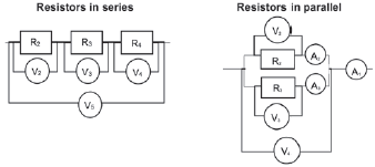
Circuits can be connected into two ways: Series and Parallel. A series circuit requires the electricity to travel one path that does not split. A parallel circuit allows the electricity to go down different paths (there’s a split in the circuit). See the diagrams below showing resistors in series and parallel for an illustration.
Resistors in a circuit
| |
| Work is done in a resistor when the electric energy is transformed to heat energy or to light energy. | |
|
|
Learn the factors influencing the resistance of a wire conductor. It will help when explaining your answer in an exam.
7.2.2 Comparison between series and parallel circuits
| Series connection | Parallel connection |
| I1 = I2 = I3… The total current across the series is the same. | V1 = V2 = V3… The total voltage across the parallel component is the same. |
| VT = V1 + V2 + V3… This is a potential divider. | IT = I1 + I2 + I3… This is a current divider. |
| RT = r1 + r2 + r3… Addition of resistors. | 1 =1 + 1 + ... Rf r1 r2 Addition of the ratio of resistors. |
7.3 Voltage (Potential Difference) and Electromotive Force (emf)
- Voltage in which the charge is losing energy is a potential difference, V.
- Voltage in which the charge is gaining energy is an electromotive force (emf), ε
- Therefore the voltage across the battery is an electromotive force (emf), while the voltage across each resistor is potential difference (p.d).
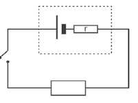
7.4 Internal Resistance
- When the switch is open, the voltmeter reads the emf of the battery which is 12,5 V. This means the battery can transfer 12,5 J of energy for every 1 C of charge.
- When the switch is closed, the voltmeter reads the p.d of the external circuit.
- Internal resistance is found inside the cell or battery, which is the small amount of energy that is used up inside the cell or battery.
- An ideal cell would have zero internal resistance, r = 0 Ω.
- The volts used inside the cell are referred to as the lost volts, V’.

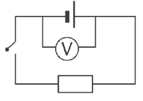
7.4.1 emf
The emf (ε) of a cell is:
- the electrical potential difference across the terminals (poles) of a cell while no current flows
- the total amount of electric energy supplied by the cell per coulomb of charge
- measured with a voltmeter connected in parallel over a cell or battery when no current flows (the switch is open)(see diagram below)
- measured in volts (V).

Formula to calculate the emf
Derivation: since R = V/I, V = IR, so if emf = V + V' (the sum of the two voltage measurements), then emf = IR + IR'. For convenience, we write IR' as Ir. Now, since I is common to both factors IR and Ir, we can take it out as a multiplier, like so: I(R+r).
Hence, emf = I(R+r).
given: emf = V + V’
∴ emf = IR + Ir
∴ emf = I (R + r)
7.4.2 Ohmic and non-ohmic conductors: differences and examples
| Ohmic conductor | Non-ohmic conductor | |
| Obeys Ohm’s Law or not? | Obeys Ohm’s Law when voltage or current is varied | Does not obeys Ohm’s Law when voltage or current is varied |
| Graph of the voltage vs. the current across conductors | 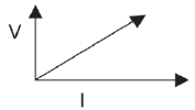 Shape: Straight line from the origin V / I = R | 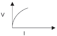 Shape: Curve V / I ≠ R |
| Examples | circuit resistors nichrome wire. | light bulb diodes transistors |
emf = 1 (R + r) is the final formula to use when calculating emf
7.5 Electric energy
When current flows or charges move through a resistor:
- electric energy is transferred from the moving charges to the particles in the resistor
- the particles in the resistor gain kinetic energy
- the temperature of the resistor increases as the kinetic energy of the particles increases.
| Formulas The work done (W) is equal to the energy (E) transferred. W = E (in joule J) W = VQ = VIt = I2Rt = V 2t R W: work done (J) joule V: potential difference (V) volt I: current (A) ampere R: resistance (Ω) ohm t: time (s) seconds |
If you are asked to calculate the amount of energy transferred, use the correct formula to calculate the work done
7.6 Power
| Definition Power is the rate at which work is done or energy is transferred. P = W = VI = I2R =V 2 Δt R P: power (W) watt W: work done (J) joule V: potential difference (V) volt I: current (A) ampere R: resistance (Ω) ohm t : time (s) seconds |
7.6.1 The brightness of light bulbs
The brightness of a light bulb is determined by the rate at which energy is transformed in the bulb, that is, by the power (P).
- As the power increases, the brightness increases.
- For bulbs in series:
P ∝ R (power is directly proportional to the resistance of the bulb)
∴ if the resistance increases, the power increases and
∴ the brightness increases. - For bulbs in parallel:
P ∝ 1 (power is inversely proportional to the resistance of the bulb)
R
∴ if the resistance decreases, the power increases and
∴ the brightness increases.
Note: the above applies to incandescent bulbs only (the type with a filament of wire).
Compact Fluorescent Lights (CFL) come in a range of power/wattages but they will simply blow if overpowered by a significant increase in voltage/ amperage.
Worked example 1
In this circuit the battery has an emf of 24 V and an internal resistance of 2 Ω. Voltmeter V1 is connected as shown and voltmeter V2 is connected over the three resistors in parallel. The resistance of the connectors and of the ammeter may be ignored.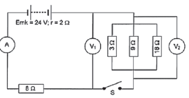
- Switch S is open.
- What is the reading on V1?
- What is the reading on V2?
- Switch S is now closed. Calculate:
- the total resistance in the circuit.
- the current that flows through the 8 Ω resistor.
- the charge that flows past a cross section of the 8 Ω resistor in one minute.
Solutions
- V1 = 24 V (when S is open, no current flows and V1 is connected across the battery)
- V2 = 0 V (S is open, no current flows, V is connected on one side of the switch, ∴ only to one pole of the battery
1 = 1 + 1 + 1 = 1 + 1 + 1 = 6 + 2 + 1 = 9
R1 R1 R2 R3 3 9 18 18 18
- Rexternal = Rseries + R|| = 8 + 2 = 10 Ω and
Rexternal = Rext + rint = 10 + 2 = 12 Ω - The 8 Ω resistor is connected in series ∴ the total current flows through it
∴ calculate the total current (I) that flows through the circuit.
Rtot = V tot
Itot
∴ 12 = 24
Itot
∴ Itot = 24 = 2 A
12 - I = Q
Δt
∴ 2 = Q
(1)(60)
∴ Q = (2)(1)(60) = 120 C
This is a current that flows through all the circuits.
- Rexternal = Rseries + R|| = 8 + 2 = 10 Ω and
Remember: Convert minutes to seconds: x 60 or hours to seconds: x 3600
Remember: Current is the rate at which electric charge passes a fixed point in a conductor.
I ∝ Q
I = Δt
Q
Activity 1
In the circuit below the battery has an emf of 24 V and an unknown internal resistance. Voltmeter V1 is connected across the battery. The resistance of the connectors and of the ammeter may be ignored. When switch S is closed, voltmeter V2 reads 4 V and voltmeter V1 reads 20 V.
- Calculate:
- The reading on ammeter A2. (2)
- The reading on ammeter A1. (5)
- The resistance of resistor R. (4)
- The internal resistance of the battery. (3)
- The energy converted in resistor R in 10 minutes. (3)
- Switch S is now opened. Will the reading on voltmeter V1 increase, decrease or remain constant? Explain. (6)
[23]
Solutions
|
Activity 2
Multiple Choice questions:
- Which ONE of the following is the unit of measurement for the rate of flow of charge?
- watt
- coulomb
- volt
- ampere (2)
- The two resistors in circuit 1 below are identical. They are connected in series to a cell of emf V and negligible internal resistance. The power dissipated by each resistor is P.

The two resistors are now connected in parallel, as shown in circuit 2 below.
The power dissipated by each resistor in the circuit 2 is...- 2P
- 4P
- 8P
- 16P (2)
[4]
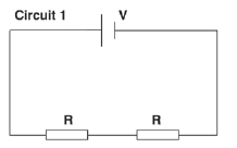
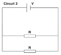
| Solutions 1. D (2) 2. B (2) [4] |
Activity 3
In the circuit represented below, the battery has an emf of 10 V and an unknown internal resistance. Voltmeter V1 is connected across the battery and voltmeter V2 is connected across the open switch S. The resistance of the connecting wires and ammeter can be ignored.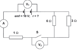
Switch S is open
- What is the reading on V1? (2)
- What is the reading on V2? (2)
When Switch S is closed, the reading on V1 drops to 7,5 V. - What is the reading on V2? (2)
- Calculate the reading on the ammeter. (8)
- Calculate the internal resistance of the battery. (5)
[19]
Solutions
|
Activity 4
The headlights of a car are connected in parallel to a 12 V battery, as shown in the simplified circuit diagram below. The internal resistance of the battery is 0,1 Ω and each headlight has a resistance of 1,4 Ω. The starter motor is connected in parallel with the headlights and controlled by the ignition switch, S2. The resistance of the connecting wires may be ignored.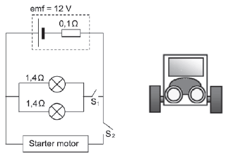
- State Ohm’s Law in words. (2)
- With only switch S1 closed, calculate the following:
- Effective resistance of the two headlights (3)
- Potential difference across the two headlights (4)
- Power dissipated by one of the headlights (3)
- Ignition switch S2 is now closed (whilst S1 is also closed) for a short time and the starter motor, with VERY LOW RESISTANCE, rotates. How will the brightness of the headlights be affected while switch S2 is closed? Write down only INCREASES, DECREASES or REMAINS THE SAME.
Fully explain how you arrived at the answer. (9)
[21]
Solutions
|