ELECTRICAL TECHNOLOGY GRADE 12 ELECTRONICS MEMORANDUM - 2018 SEPTEMBER PREPARATORY EXAM PAPERS AND MEMOS
Share via Whatsapp Join our WhatsApp Group Join our Telegram GroupELECTRICAL TECHNOLOGY: ELECTRONICS
GRADE 12
NATIONAL SENIOR CERTIFICATE
MEMORANDUM
SEPTEMBER 2018
INSTRUCTIONS TO THE MARKERS
- All questions with multiple answers imply that any relevant, acceptable answer should be considered.
- Calculations:
2.1 All calculations must show the formulae.
2.2 Substitution of values must be done correctly.
2.3 All answers MUST contain the correct unit to be considered.
2.4 Alternative methods must be considered, provided that the correct answer is obtained.
2.5 Where an incorrect answer could be carried over to the next step, the first answer will be deemed incorrect. However, should the incorrect answer be carried over correctly, the marker has to recalculate the values, using the incorrect answer from the first calculation. If correctly used, the candidate should receive the full marks for subsequent calculations.
2.6 Markers should consider that candidates' answers may deviate slightly from the marking guidelines, depending on how and where in the calculation rounding off was used. - This marking guideline is only a guide with model answers. Alternative interpretations must be considered and marked on merit. However, this principle should be applied consistently.
QUESTION 1: OCCUPATIONAL HEALTH AND SAFETY
1.1 The purpose of the Occupational Health and Safety Act is: to provide for the health and safety of persons at work and the health and safety of persons in connection with the use of plant and machinery; ✓✓ the protection of persons other than persons at work against hazards to health and safety arising out of or in connection with the activities of persons at work. ✓✓ (2)
1.2 Alternating current (AC) such as from the main supply, causes the muscles in the body to contract ✓✓ and if the current is high enough one would not be able to ‘let go’ of the live wire causing the electric shock. ✓✓Typical ‘let go’ current is about 0,007 ampere (7 milli-amp). (2)
1.3
- Faulty tools or equipment ✓
- Poor ventilation
- Poor or missing guards
- Excessive noise
- Lack of knowledge of emergency procedures
(Any relevant answer) ✓✓ (1)
1.4
- Horseplay✓
- Running in the workshop
- Throwing things around
- Leaving bags, stools or material in walkway
- Spilling a liquid or oil without cleaning
(Any relevant answer) ✓✓(1)
1.5
- Keep the person lying down
- Cover the person to maintain body heat✓
- Don’t move the person in case of neck or spine injuries
- If unconscious, put them on their side (recovery position)
- Keep a close watch on the patient’s colour, raising the head or legs to manage blood flow into the paler areas
(Any TWO relevant answers) ✓✓ (2)
[8]
QUESTION 2: RLC
2.1
2.1.1 Z = √R2 + (XL - XC)2
= √122 +(24 - 18)2
=13, 42Ω(3)
2.1.2 IT = VT
Z
= 30
13.42
= 2.24A
2.1.3 VR = IT x R
= 2.24 x 12
= 26.88V
VL = IT x XL
= 2.24 x 24
53.76V
VC = IT x XC
= 2.24 x 18
= 40.32V (6)
2.1.4
cosθ = R
Z
θ = cos-1 R
Z
θ = cos-1 12
13.42
θ = 26.6º (3)
2.1.5 VT = √V2R + (VL - VC)2
= √26.882 + (53.76 - 40.32)2
= 30V (3)
2.1.6 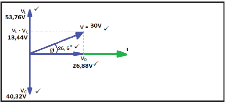 (5)
(5)
2.2
2.2.1 IT =√I2R + (IL - IC)2
= √152 + (15 - 10)2
= 15.81A (3)
2.2.2 XL = VT
IL
= 240
15
= 16Ω (3)
2.2.3 XL = 2πfL
L = X L
2πf
L = 16
2πx50
L = 0.05H or 50mH (3)
2.3
2.3.1 Resonance in an RLC circuit is a condition at a specific frequency where XL = XC.✓ This results in the current and voltage to be in phase therefore a phase angle of 0o.✓✓ (2)
2.3.2 Q-factor in a parallel circuit is the relationship between the resistance✓ and the reactance of the circuit.✓✓ (2)
2.4
2.4.1 C = 1
2πfXC
C = 1
2π x 50 x 157
C = 20.27μF (3)
2.4.2 Q = X L
R
Q = 157
4
Q = 39.25 (3)
[42]
QUESTION 3: SEMICONDUCTORS
3.1 A FET is a voltage controlled device ✓ (1)
3.2
3.2.1 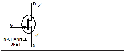 (3)
(3)
3.2.2
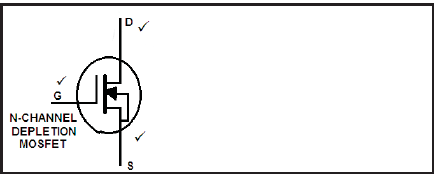 (3)
(3)
3.3 The main advantage of a FET over BJT is that it has significantly lower levels of power loss making it more efficient. ✓✓ (2)
3.4 A signal applied to the non-inverting terminal will appear at the output terminal in the same direction as when it entered the op-amp. ✓
A signal applied to the inverting terminal will appear at the output terminal in an inverted direction to when it entered the op-amp. ✓ (2)
3.5  (3)
(3)
3.6 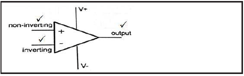 (3)
(3)
3.7
- Distortion of the output signal is reduced ✓
- The amplifier circuit gain will be reduced ✓
- The amplifier becomes much more stabilised ✓
- The rage of frequencies which can be amplified is increased (3)
3.8
3.8.1 Inverting op-amp ✓ (1)
3.9 AV = 1 + R F
Rin
AV = 1 + 150 000
15 000
AV = 11(3)
3.10
- Astable mode
- Bistable mode
- Monostable mode (3)
3.11  (4)
(4)
3.12 η = rb1
rb1 - rb2
η = 5 000
5 000 + 2 000
η = 0.714 (3)
[34]
QUESTION 4: SWITCHING CIRCUITS
4.1
- Monostable multivibrator ✓
- Bi-stable multivibrator ✓
- Astable multivibrator ✓ (3)
4.2
4.2.1 Bi-stable multivibrator ✓ (1)
4.2.2
- This op amp operates as a comparator. ✓
- Any difference between its two input causes its output to go into either positive saturation (+VSAT) or negative saturation (-VSAT). ✓
- The non-inverting input is fed by a fraction of the output voltage fed-back from the voltage divider pair of R2 and R3. ✓
- If the output voltage is high (+VSAT) then the non-inverting terminal voltage will be a smaller positive voltage✓and if the output is low (-VSAT) the non-inverting input terminal voltage will be a smaller negative voltage. ✓ (4)
4.3
- De-bouncing ✓
- Varying the time period ✓ (2)
4.4 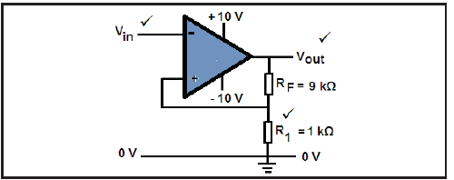 (3)
(3)
4.5
- It is widely used in the first stages of many radio receivers, especially in digital applications where it is used to clean up a signal which has been distorted of which has had some noise added during its transmission through the air. ✓
- In digital circuitry noise is often introduced into a system via switch bounce which can cause a number of unwanted voltage spikes to appear during the switching-on period. ✓
- Varying input waveforms, for example a sine wave can be changed into a square or rectangular wave. ✓
- A signal can be successfully recovered using a Schmitt trigger even after having suffered severe distortion as the circuit will only sense a single level change, so eliminating all other noise spikes. ✓ (4)
4.6 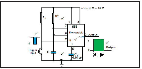 (5)
(5)
4.7 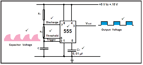 (6)
(6)
4.8 Vout = -(V1 R F + V2 R F + V3 R F)
R1 R2 R3
Vout = -(100mV x 100kΩ + 200mV 100kΩ + 300mV x 100kΩ )
20kΩ 10kΩ 50kΩ
Vout = 3.1V (3)
4.9
4.9.1  (4)
(4)
4.10
4.10.1 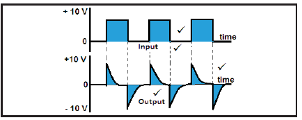 (4)
(4)
4.11
- The op-amp’s inputs draw zero current so any input current is passed through to the feedback circuit. ✓
- The op-amp’s two inputs are viewed as both possessing the same voltage at all times,✓ if the lower input is connected to ground, this introduces the virtual earth concept. ✓
- When a constant current is fed to a capacitor, it will charge at a constant fixed rate rather than exponential.✓ (3)
4.12 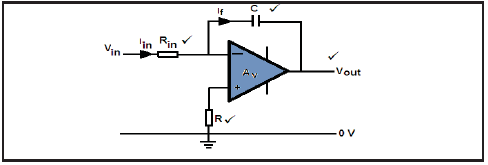 (4)
(4)
4.13
4.13.1 ?ℎ???i?? ?i?e = 0, 693 (?1 + ?2) × ?
= 0, 693(470 × 103 + 5 × 103) × 1 × 10−6
= 0, 33 ?e?(3)
4.13.2 ?i??ℎ???i?? ?i?e = 0, 693 × ?1 × ?
= 0, 693 × 5 × 103 × 1 × 10−6
= 3, 47?i??i ?e?o???(2)
4.13.3 ? = ?1 + ?2
= 0, 33 + 3, 47 × 10−3
= 0, 33 ?e? (3)
4.13.4 ƒ = 1 = 1,44
? (?1− 2?2)×?
= 1,44
(470×103×+2×5×103)×1×10−6
= 3?z (3)
[58]
QUESTION 5: AMPLIFIERS
5.1 Amplifier is an electric device that is used to increase✓ voltage, power or current signal.✓ (2)
5.2  (8)
(8)
5.3  (4)
(4)
5.4 To operate as an amplifier a transistor must be biased to operate only in its active region. ✓ (1)
5.5 These amplifiers are biased in such a way that each of the transistors only engage with to amplify and conduct for one half of the input cycle. ✓✓✓
Class B amplifiers conducts for 180° of the input signal.✓ (2)
5.6 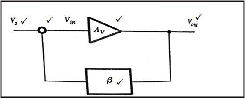 (5)
(5)
5.7
- Poor frequency response ✓
- Increase cost ✓
- Gain is constant over only a small range of frequencies ✓
- Low frequencies receive less amplification than high frequencies
(Any THREE) (3)
5.8
- RC communications ✓
- Optimal fibre communications ✓
- Public address system as pre-amplifier ✓
- Radio / TV receivers (3)
5.9 5.9.1 Transformer coupled amplifier ✓ (1)
5.9.2 Matching the audio amplifier with a low impedance loudspeaker ✓ (1)
5.9.3 It makes use of the inductive coupling properties of the transformer to couple 2 stages together. ✓✓It matches 2 different impedances while at the same time separating the DC circuits ✓ and acts as a buffer. ✓ (3)
5.10 Both circuits use LC tank circuits: ✓ the Hartley oscillator uses a single capacitor with two inductors with their centre point coupled to the emitter.✓
The Colpitts oscillator uses a single inductor with two capacitors,✓✓✓with their centre point coupled to the emitter. ✓ (4)
5.11 Given : ?1 = 600??,?2 = 20??, ?? = 10???
?? = ?1 ×?2
?1+ ?2
= 600×10−9 × 20 × 10−6
600×10−9 + 20×10−6
= 582.5 10−9?
? = ( 1 )2 x ( 1 )
2?ƒ ??
=( 1 )2 x ( 1 )
2?10×103 582.5× 10−9
= 432,9?? (5)
5.12 Given : ? ?i?= 100??, ???? =500??, ? = 20?Ω
?? ??? = 1
2?√6??
= 1
2? √6 20 ×103 × 500×10−12
= 6,5???
?? ?i? = 1
2?√6??
= 1
2? √6 20× 103 ×100 ×10−12
= 32,5??? (4)
5.13
5.13.1 Hartley LC tank circuit with two inductors ✓
5.13.2 Collpitts LC tank with two capacitors ✓
5.13.3 RC Three RC phase shifting circuits ✓ (3)
5.14 General entertainment ✓
RF direction finding equipment ✓
Communication system ✓ (3)
5.15 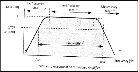 (6)
(6)
[58]
TOTAL: 200