MECHANICAL TECHNOLOGY PAPER 2 GRADE 12 (FITTING AND MACHINING) QUESTIONS - 2018 SEPTEMBER PREPARATORY EXAM PAPERS AND MEMOS
Share via Whatsapp Join our WhatsApp Group Join our Telegram GroupMECHANICAL TECHNOLOGY: FITTING AND MACHINING
GRADE 12
NATIONAL SENIOR CERTIFICATE
SEPTEMBER 2018
INSTRUCTIONS AND INFORMATION
- Write your NAME on your ANSWER BOOK.
- Read ALL the questions carefully.
- Answer ALL the questions.
- Number the questions correctly according to the numbering system used in this question paper.
- Start EACH question on a NEW page.
- Show ALL calculations and units. Round off final answers to TWO decimal places.
- Candidates may use non-programmable scientific calculators and drawing instruments.
- The value of gravitational acceleration should be taken as 10 m/s2.
- All dimensions are in millimetres, unless stated otherwise in the question.
- A formula sheet for your use is attached at the back of this question paper.
- Write neatly and legibly.
- Use the criteria below to assist you in managing your time management.
| QUESTION | CONTENT COVERED | MARKS | TIME |
| Generic | |||
| 1 | Multiple-choice questions | 6 | 6 minutes |
| 2 | Safety | 10 | 10 minutes |
| 3 | Materials | 14 | 14 minutes |
| Specific | |||
| 4 | Multiple-choice questions | 14 | 10 minutes |
| 5 | Terminology (Lathe and milling machine) | 18 | 20 minutes |
| 6 | Terminology (Indexing) | 28 | 25 minutes |
| 7 | Tools and Equipment | 13 | 10 minutes |
| 8 | Forces | 33 | 33 minutes |
| 9 | Maintenance | 18 | 12 minutes |
| 10 | Jointing Methods | 18 | 12 minutes |
| 11 | Systems and Control (Drive systems) | 28 | 28 minutes |
| TOTAL | 200 | 180 minutes | |
QUESTION 1: MULTIPLE-CHOICE QUESTIONS (GENERIC)
Various options are provided as possible answers to the following questions. Choose the correct answer and write only the letter (A–D) next to the question number (1.1–1.6) in the ANSWER BOOK, for example 1.7 A.
1.1 Which of the following laws in South Africa protect the people living with HIV/Aids?
- Occupational Health and Safety Act (OHS)
- The Bill of Rights
- The Labour Relations Act
- All of the above (1)
1.2 Identify the safety measure below that is applicable to the bench grinder in terms of the Occupational Health and Safety Act.
- All surfaces of the machine must be well oiled.
- Guards must be removed when grinding.
- Wear safety goggles when grinding.
- Ensure that the machine is running. (1)
1.3 The following safety precautions must be followed when handling gas bottles.
- Wear approved PPE to shield the skin from the arc rays.
- Use completely insulated electrode holders.
- Wear leather spats and safety boots when welding.
- Never stack cylinders on top of one another. (1)
1.4 The process of relieving stresses, set up by cold working is termed …
- annealing.
- hardening.
- tempering.
- normalising. (1)
1.5 Materials can be tested differently in the workshop and industry.
How can metals be tested?
- Sound test
- Bend test
- Filing test
- All of the above (1)
1.6 Which of the following carbon steels has short, very white or light yellow carrier lines with forking and considerable many star- like bursts?
- Low carbon steel
- High carbon steel
- Cast iron
- Medium carbon steel (1)
[6]
QUESTION 2: SAFETY (GENERIC)
2.1 List FOUR unsafe conditions in a mechanical workshop. (4)
2.2 Describe at least some of the procedures to follow when assessing a first-aid situation. (2)
2.3 Give the advantages of the following workshop layouts:
2.3.1 Product layout of machines (2)
2.3.2 Process layout of machines (2)
[10]
QUESTION 3: MATERIALS (GENERIC)
3.1 State the purpose of case-hardening mild steel. (2)
3.2 The hardness that can be achieved with a given heat treatment depends on three factors. Mention the THREE factors. (3)
3.3 List FOUR kinds of quenching mediums. (4)
3.4 Why is it important that hardened steel be tempered during the heating process, as soon as possible? (2)
3.5 Tabulate the findings on the different tests on the materials indicated below.
| Material | |||
| Type of test | Mild Steel | High Speed Steel | Cast Iron |
| Sound Test | 3.5.1 | 3.5.2 | 3.5.3 |
(3)
[14]
QUESTION 4: MATERIALS (SPECIFIC)
Various options are provided as possible answers to the following questions. Choose the correct answer and write only the letter (A–D) next to the question number (4.1–4.14) in the ANSWER BOOK, e.g. 4.15 A.
4.1 The lathe operates on the principle of ...
- the cutter revolving against the workpiece.
- the cutting tool, that can be controlled, can be moved vertically across the work piece.
- the work piece rotating against the cutting tool, which can be controlled.
- both cutter and workpiece rotating. (1)
4.2 Identify the milling process in FIGURE 4.2 below.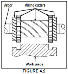
- Gang milling
- Slab milling
- Straddle milling
- Up-cut milling (1)
4.3 Which ONE of the following is an advantage of down-cut milling?
- The finish obtained is finer
- Coarse feed may be used
- Vibration experienced is less
- The strain on the cutter and arbor is less (1)
4.4 In terms of lathes and milling machines, what does the abbreviation CNC stand for.
- Computer National Control
- Computerised Numerical Control
- Curriculum National Code
- None of the above (1)
4.5 What does the symbol “d” denote in the Brinell hardness test shown in FIGURE 4.5 below?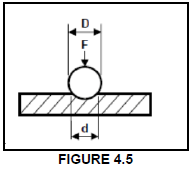
- Ball diameter
- Hardness number
- Test piece
- Indentation diameter (1)
4.6 In a tensile test …
- a test piece is loaded to destruction.
- beams are used to determine the structure of a weld.
- a hammer is used to break the test material.
- liquid dye is used to detect weld flaws. (1)
4.7 The unit for compressive stress is …
- newton (N).
- metre (m).
- pascal (Pa).
- watt (W). (1)
4.8 … are products made from polyvinyl chloride (PVC).
- Ceramic tiles and window frames
- Wedding rings and metal chains
- Boats and bicycle frames
- Water pipes, building material and food packaging (1)
4.9 Thermoplastics are materials that …
- can be stretched but rapidly return to their original shape.
- soften under heat and become hard when cooled.
- form a rigid shape under pressure or heat.
- are used to manufacture bicycle frames. (1)
4.10 Determine the width of a key if the diameter of the shaft is 60 mm.
- 15 mm
- 30 mm
- 20 mm
- 6 mm (1)
4.11 A compressive test needs to be done on a round stepped shaft, shown in FIGURE 4.11 below.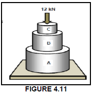
Identify the area in which the maximum stress will occur.
- Part C
- Part A
- Part B
- Equal stress in all three parts (1)
4.12 What is meant by the term Young’s modulus of elasticity?
- The measurement of extension or contraction of a bar when an external load is applied.
- Stress value required to produce unit strain in a tensile specimen of the particular material.
- Strain is directly proportional to the stress it causes, provided the limit of proportionality is not exceeded.
- A measurement of the deformation produced by the application of the external forces. (1)
4.13 What will be the deformation of a bar, that is 0,73 m long when the strain is 0,5 x 10^-3?
- 0,653 mm
- 0,036 mm
- 0,498 mm
- 0,365 mm (1)
4.14 Identify the symbol, shown in FIGURE 4.14 below, which relates to a pneumatic system.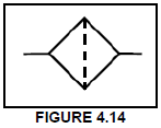
- Valve
- Filter
- Compressor
- Motor (1)
[14]
QUESTION 5: TERMINOLOGY (LATHE AND MILLING MACHINE) (SPECIFIC)
5.1 A spindle needs to be turned according to the dimensions given below in FIGURE 5.1.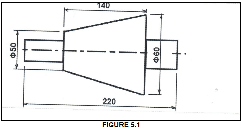
Calculate each of the following:
5.1.1 The amount of tailstock set-over (3)
5.1.2 The included angle of tapered portion (in degrees) (1)
5.2 On which part of the lathe would each of the following attachments be mounted:
5.2.1 Fixed steady (1)
5.2.2 Travelling steady (1)
5.3 Define the pitch of screw thread. (2)
5.4 Give the reason for using a dividing head on a milling machine. (1)
5.5 Explain the taper-turning procedure using the compound-slide method. (5)
5.6 Make a neat sketch of a square-thread cutting tool, showing the tool in the square groove. Indicate the helix angle, clearance angle, leading tool angle and the following tool angle on your sketch. (5)
[19]
QUESTION 6: TERMINOLOGY (INDEXING) (SPECIFIC)
6.1 Two gears that mesh with each other need to be manufactured. The one gear should have 56 teeth with a PCD of 126 mm, while the other gear should have 39 teeth with a PCD of 87,75 mm.
Determine, by means of calculations, the following:
6.1.1 The module of the small gear (2)
6.1.2 The module of the large gear (2)
6.1.3 The outside diameter of the large gear (3)
6.1.4 The dedendum of the large gear (2)
6.1.5 The clearance of the gear system (2)
6.1.6 The indexing needed to cut the smaller gear (39 teeth) (4)
6.2 Explain the function of an index plate as used during differential indexing. (2)
6.3 Calculate the indexing movement for 61 20’. (3)
6.4 Define the term module as applied to gears. (2)
6.5 Two precision rollers are placed inside a dovetail as shown in FIGURE 6.5 below. Use the given information and calculate the measurement of the widest part x of the dovetail. Depict the diameter of the rollers using standard drawing practice. (6)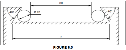
[28]
QUESTION 7: TOOLS AND EQUIPMENT (SPECIFIC)
7.1 Describe the principle of testing (procedure) followed when the Brinell hardness testing equipment is used. (4)
7.2 State TWO properties of materials that can be determined by performing a tensile test using a tensile tester. (2)
7.3 Calculate the pitch diameter of the following I.S.O screw thread:
7.3.1 M 22 x 2, 5 (2)
7.4 State the function of the screw thread micrometre. (2)
7.5 What is the reading on the depth micrometre shown in FIGURE 7.5 below? (3)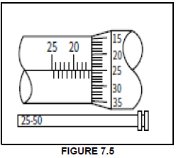
[13]
QUESTION 8: FORCES (SPECIFIC)
8.1 Four forces of 150 N, 210 N, 250 N and 360 N, as shown in FIGURE 8.1 below, act on the same point. Calculate the magnitude and direction of the resultant force for this system of forces.(12)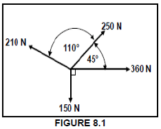
8.2 The diagram in FIGURE 8.2 below shows a uniform beam supported by two vertical supports, A and B. Two vertical point loads, as well as a uniformly distributed force of 60 N/m over the distance between the two vertical point loads are exerted onto the beam.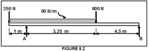
8.2.1 Define moment of force. (1)
8.2.2 Determine, by means of calculations, the magnitude of the reactions in support A and support B. (7)
8.2.3 List TWO beam applications (uses) you know. (2)
8.3 A brass bush, 80 mm long with an inside diameter of 30 mm and an outer diameter of 40 mm, is used in a press to push out bearings. A force of 23 kN is exerted onto the bush.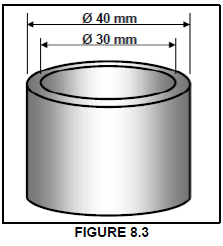
8.3.1 Name the type of stress that the bush material is subjected to. (1)
8.3.2 Calculate the stress in the material. Indicate the answer in MPa. (5)
8.3.3 Calculate how much the bush will shorten under the given load, if Young’s modulus of elasticity for brass is 90 GPa. (5)
[33]
QUESTION 9: MAINTENANCE (SPECIFIC)
9.1 Explain briefly how basic preventative maintenance should be performed on the following:
9.1.1 Gear systems (1)
9.1.2 Belt systems (1)
9.1.3 Chain drive systems (1)
9.2 Give THREE reasons for using cutting fluid when working on the centre lathe. (3)
9.3 Define the term pour point of a lubricant. (1)
9.4 How can friction be reduced when drilling holes? (1)
9.5 Tabulate TWO properties and TWO uses for each of the following composites:
9.5.1 Vesconite (4)
9.5.2 Carbon fibre (4)
9.6 What is the difference between static and sliding coefficient of friction? (2)
[18]
QUESTION 10: JOINING METHODS (SPECIFIC)
10.1 The diagram in FIGURE 10.1 below shows a metric V-screw thread. Label parts A–G. (7)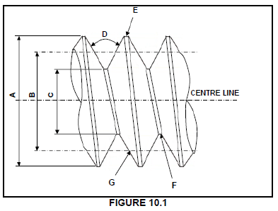
10.2 The length of the parallel key is 102 mm.
Calculate the following:
10.2.1 The diameter of the shaft (2)
10.2.2 The width of the key (2)
10.2.3 The thickness of the key (2)
10.3 Why would a multi-start thread be preferred in some instances to single-start thread? (1)
10.4 A M8 x 1,5 screw thread is to be cut on a lathe.
Calculate the following:
10.4.1 The depth of a thread (1)
10.4.2 The height of the screw thread (1)
10.5 List TWO uses of a square thread. (2)
[18]
QUESTION 11: SYSTEMS AND CONTROL (DRIVE SYSTEMS) (SPECIFIC)
11.1 Name the TWO factors that would determine the use of gear drives in the industry. (2)
11.2 A technical school teacher requires a hydraulic press to be purchased for her new engineering workshop. The force applied on piston A is 550 N. Piston A moves 60 mm downwards. The diameter of piston B is 180 mm and moves up by 12 mm.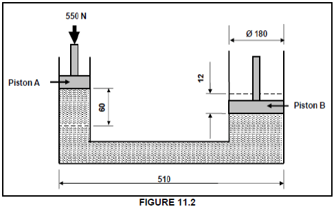
Use the specifications shown in FIGURE 11.2 and calculate the following:
11.2.1 The diameter of piston A (dA) (4)
11.2.2 The pressure exerted on piston A (2)
11.3 What is the main difference between a pump and a motor in a hydraulic system? (4)
11.4 Give the function of the following pneumatic components:
11.4.1 Air receiver (1)
11.4.2 Pipes (1)
11.4.3 Actuator (1)
11.5 The belt-drive system of a water pump is shown in FIGURE 6.2. The driver pulley on the electrical motor has a diameter of 118 mm and rotates at
1 440 r/min while the driven pulley has a diameter of 230 mm.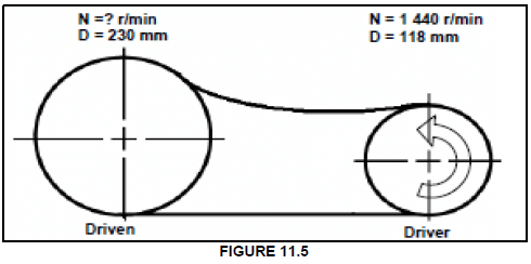
Determine by means of calculations the following:
11.5.1 The rotation frequency of the driven pulley in r/min (3)
11.5.2 The belt speed of the system in metres per second (2)
11.6 A driver gear on the shaft of an electrical motor has 30 teeth and meshes with a gear on a countershaft which has 80 teeth. There is a driver gear with 40 teeth on the countershaft that meshes with the final driven gear, which has 63 teeth and rotates at 2 r.s-1. Draw a diagrammatical representation of the gear system to assist you with the calculations below.
Determine by means of calculations:
11.6.1 The rotation frequency of the electrical motor (4)
11.6.2 The speed ratio of the gear train (2)
11.7 Name TWO parts of a chain system. (2)
[28]
TOTAL: 200
FORMULA SHEET FOR MECHANICAL TECHNOLOGY (FITTING AND MACHINING)
Force = m x a
where m = mass
a = acceleration
Work = force x distance( F x d)
Power = force x distance
time
Torque = force x radius
Indicated power = P x L x A x N x n
where P mean effective pressure
L length of stroke
A area of piston crown
N number of power strokes per second
n number of cylinders
Brake power 2 x π x N x T
where N = revolutions per second
T = torque
Brake power (P rony brake) F x 2 x π x R x N
where F force
R length of brake arm
N revolutions per second
Mechanical efficiency = brake power x 100
indicated power
Compression ratio= swept volume + clearance volume
clearance volume
where swept volume = π x D2 L
4
where L length of stroke
D = diameter of bore
Clearance volume = π x D2 x I
4
where D = diameter of bore
l = clearance
Gear ratio= product of the number of teeth of the driven gears
product of the number of teeth of the driver gears