MECHANICAL TECHNOLOGY PAPER 2 GRADE 12 (FITTING AND MACHINING) MEMORANDUM - 2018 SEPTEMBER PREPARATORY EXAM PAPERS AND MEMOS
Share via Whatsapp Join our WhatsApp Group Join our Telegram GroupMECHANICAL TECHNOLOGY: FITTING AND MACHINING
GRADE 12
NATIONAL SENIOR CERTIFICATE
MEMORANDUM
SEPTEMBER 2018
QUESTION 1: MULTIPLE-CHOICE QUESTIONS
1.1 D ✓ (1)
1.2 C ✓ (1)
1.3 D ✓ (1)
1.4 D ✓ (1)
1.5 D ✓ (1)
1.6 B ✓ (1)
[6]
QUESTION 2: SAFETY
2.1 Unsafe conditions:
- Working at unsafe speeds. ✓
- Grinding without goggles. ✓
- Fooling and playing around workshop. ✓
- Spilling liquids on floor. ✓
- Lubricating/cleaning moving parts. ✓
- Wearing loose clothing near moving parts. ✓
- Grinding on the side of the grinding wheel. ✓ (Any 4) (4)
2.2 Assessing a first aid situation:
- Environmental observation. ✓
- Visible signs and symptoms. ✓
- Indicators to diagnosis. ✓
- Vital functions. ✓
- Stopping any serious bleeding. ✓
- Immediate treatment of cardiac arrest. ✓ (Any 2) (2)
2.3.1 Advantages of product layout:
- Handling of material is limited to a minimum. ✓
- Time period of manufacturing cycle is less. ✓
- Production control is almost automatic. ✓
- Greater use of unskilled labour is possible. ✓
- Less total inspection is required. ✓
- Less total floor space is needed per unit of production. ✓ (Any 2) (2)
2.3.2 Advantages of the process layout of machines
- High machine utilisation because more than one product is manufactured. ✓
- Better supervision as a result of subdivision of processes. ✓
- Less interruption in flow of work when machines become defective. ✓
- Lower equipment cost, since one machine can produce more than one product. ✓
- Better control of total manufacturing cost. ✓
- Greater flexibility in the production process. ✓ (Any 2) (2)
[10]
QUESTION 3: MATERIALS
3.1 Purpose of case-hardening.
The objective is to produce a hard case over a tough core. ✓✓ (2)
3.2 Factors of hardness.
- Workpiece size. ✓
- Quenching rate.✓
- Carbon content. ✓ (3)
3.3 Four kinds of quenching mediums.
- Water and salt (brine) ✓
- Tap water ✓
- Liquid salts ✓
- Molten lead ✓
- Soluble oil and water ✓
- Oil ✓ (Any 4) (4)
3.4 Reason for hardened steel to be tempered:
To reduce brittleness✓ and to give the work piece a more fine-grained structure. ✓ (2)
3.5 Test on materials:
| Type of test | Mild Steel | High Speed Steel | Cast Iron |
| Sound Test | Medium metallic sound ✓ | Low ring sound ✓ | Dull sound ✓ |
(3)
[14]
QUESTION 4: MULTIPLE-CHOICE QUESTIONS (SPECIFIC)
4.1 C ✓ (1)
4.2 C ✓ (1)
4.3 A ✓ (1)
4.4 B ✓ (1)
4.5 A ✓ (1)
4.6 A ✓ (1)
4.7 C ✓ (1)
4.8 D ✓ (1)
4.9 B ✓ (1)
4.10 A ✓ (1)
4.11 B ✓ (1)
4.12 C ✓ (1)
4.13 D ✓ (1)
4.14 B ✓ (1)
[14]
QUESTION 5: TERMINOLOGY (LATHE AND MILLING MACHINE) (SPECIFIC)
5.1 Tailstock set-over
5.1.1 ??? − ???? = ?−? × ?????ℎ ?????????
2 ?????ℎ ?? ????? √
= 60−50 × 220 √
2 140
= 7,857 mm √ (3)
5.1.2 ??? ? = 5
2 140
? = ???−1 0.0357 = 2.045 ✓
2
θ = 4,1 √ (1)
5.2 Lathe attachments:
5.2.1 Lathe bed √ (1)
5.2.2 Lathe carriage √ (1)
5.3 The pitch (P) of a screw thread is the distance from any point on the screw thread to a corresponding point on an adjacent (next) thread, measured parallel to the axis of the screw thread. √ (1)
5.4 The reason for using a diving head on a milling machine is to divide the circumference of a circular object into any number of equal divisions. √ (1)
5.5 Taper-turning procedure:
- The base of the compound slide or top of the cross slide comprises a circular plate that is marked off in degrees. √
- Loosen the base screws and set the compound slide to the desired angle. √
Tighten the screws to lock it into position. √ - The tool should be set with its cutting point exactly level with the lathe’s centre line. √
- The carriage should always be locked to the lathe bed when cutting short tapers. √
- When the cutting action has started, use the compound slide handle to feed. √ (Any 5 x 1) (5)
5.6 Square screw thread: ✓ (5)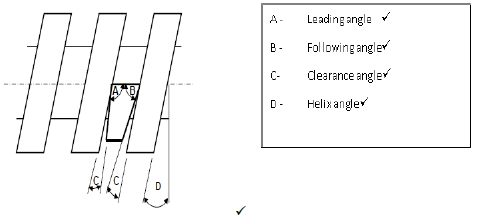
[18]
QUESTION 6: TERMINOLOGY (INDEXING) (SPECIFIC)
6.1 Gear calculations:
6.1.1 Module of small gear:
?????? (?) = ???
?
m = 87,75
39 ✓
m = 2,25 mm ✓ (2)
6.1.2 Module of Large gear:
?????? (?) = ???
?
= 126/56 ✓
= 2,25 mm ✓ (2)
6.1.3 Outside Diameter of larger gear:
OD = PCD + 2m ✓
OD = 126 + (2 x 2,25) ✓
= 130,50 mm ✓ (3)
6.1.4 Dedendum of large gear:
D = 1,157 x m OR D = 1,25 x m
= 2,6 mm √√ = 2,81 mm √√ (2)
6.1.5 Clearance of gear system:
C = 0,157 x m OR C = 0,25 x m
= 0,35 mm √√ = 0,56 mm √√ (2)
6.1.6 Indexing on the large gear:
???????? = 40
?
= 40/39✓
= 1 1 ✓
39
One turn of the crank handle, ✓ One hole, on a 39 hole plate ✓ (4)
6.2 The index plate makes provision for diving a fraction of a turn accurately by means of holes spaced evenly on the pitch circle. ✓✓ (2)
6.3 ??????? ???????? = ????? ???????? (???????)
9
??????? ????????, ? = ????? ???????? (???????)
540
= 61✓ 20 ‘/9 ✓
= 3680/540
= 6 44 ✓
54
i.e. 6 complete turns of the crank and 44 holes in the 54 hole circle. ✓ (3)
6.4 Module is the ratio ✓ of pitch diameter to the number of the teeth, generally regarded as tooth size. ✓ (2)
6.5 Dovetail Calculations:
? = ? = 10 ??✓
2
? = ? = 20°✓
2
tan ? = ? ✓
?
X = 2a + 2R + 80 ✓
X = (2 x 27,5) + (2 x 10) + 80 ✓
= 154,95 mm ✓ (6)
[28]
QUESTION 7: TOOLS AND EQUIPMENT (SPECIFIC)
7.1 Brinell Principle:
The Brinell Hardness Test involves indenting ✓ the test material with a piece of 10 mm hardened steel or carbide ball, ✓ subjected to a load of 3 000 kg.
For softer materials, the load can be reduced to 1 500 kg or 500 kg to avoid excessive indentation. The full load is normally applied ✓ for 10 to 15 seconds in the case of iron and steel and for at least 30 seconds in the case of other metals. The diameter of the indentation left in the test material is measured with a low-powered microscope. ✓
The Brinell Hardness Number is determined by dividing the load applied by the surface area of the indentation. (4)
7.2 Properties:
- Yield strength √
- Ultimate tensile strength √
- Elongation percentage √ (Any 2 x 1) (2)
7.3 Pitch Diameter:
Dp = Dn – (0,866 × Pitch)
= 22 – (0,866 x 2,5) ✓
=19,835 mm ✓ (2)
7.4 Screw Thread Micrometer:
The screw-thread micrometer is specifically designed to measure the pitch diameter of a screw thread. ✓✓ (2)
7.5 Depth Micrometer Reading: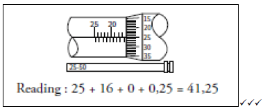
(3)
[13]
QUESTION 8: FORCES (SPECIFIC)
8.1 Resultant Force Calculations: (12)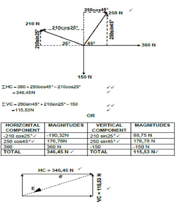
8.2 Moments: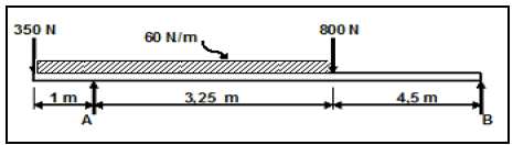
FIGURE 8.2
8.2.1 Define moment of force.
Moment of force is defined as force applied at a perpendicular distance. √ (1)
8.2.2 Calculations, the magnitude of the reactions in support A and support B.
Convert UDL to a point load: 60 N/m x 4,25 m = 255 N √
Taking moments around A
(255 x 1,125) + (800 x 3,25) = (B x 7,75) + (350 x 8,75) ✓
286,88 + 2600 = 7,758 + 350
B = 2536,88 ÷7,75 ✓
B = 327,34 N ✓
Taking moments around B
(A x 7,75) = (800 x 4,5) + (255 x 6,625) + (350 x 8,75) ✓
= 3600 + 1689,38 + 3062,5
A = 8351,88 ÷ 7,75 ✓
A = 1077,66 N ✓ (7)
8.2.3 Beam applications:
- Bridges ✓
- Truss ✓
- Desks ✓
- Railway lines ✓ (Any 2 x 1) (2)
8.3 Stress Calculations:
8.3.1 Compressive Stress ✓ (1)
8.3.2 Stress in material:
A = ?(?2−?2)✓
4
= ?(0,042−0,032)✓
4
= 0,55 x 10⁻³ ?2 ✓
? = ?
?
= 23 ? 10 3
0,55 ? 103 ✓
= 41,84 MPa ✓ (5)
8.3.3 Shortening of bush:
? = ?
?
= 41,82 × 10⁶
90 × 109 ✓
= 0,46 X 10⁻³ ✓
∆? = ol x E ✓
= 80 x (0,46 X 10−3) ✓
= 36,8 x 10⁻³ mm ✓ (5)
[33]
QUESTION 9: MAINTENANCE (SPECIFIC)
9.1 Basic preventative maintenance:
9.1.1 Gear systems:
- Checking and replenishment of lubrication levels. ✓
- Ensuring that gears are properly secured to shafts. ✓
- Cleaning and replenishment of oil filters. ✓
- Reporting excessive noise and wear, vibration and overheating to be reported. ✓ (Any 1) (1)
9.1.2 Belt drive systems check:
- For wear and tear on belt. ✓
- Belt alignment. ✓
- Tension setting. ✓
- The tensioning devices e.g. jockeys ✓ (Any 1) (1)
9.1.3 Chain drive systems:
- Cleaning uncovered chain drives. ✓
- Check sprocket teeth and link plate wear. ✓
- Refilling reservoir’s lubricants. ✓
- Checking the function of tensioning devices. ✓
- Inspect chains regularly for elongation and record the results. ✓
(Any 1) (1)
9.2 Reasons for using cutting fluid when working on the centre lathe:
- It prevents the shavings or metal chips from sticking and fusing to the cutting tool. ✓
- It will carry away the heat generated by the turning process. ✓
- It flushes away shavings/metal chips. ✓
- It improves the quality of the finish of the turned surface. ✓ (Any 3 x 1) (3)
9.3 Pour point of a lubricant:
Is the lowest temperature at which a lubricant will cease to flow. ✓ (1)
9.4 By applying a cutting fluid during the cutting action. ✓ (1)
9.5 TWO properties and TWO uses of each composites:
| Composite | Properties | Uses |
| 9.5.1 Vesconite |
|
|
| 9.5.2 Carbon Fibre |
|
|
9.6 The difference between static and sliding coefficient of friction:
Static coefficient of friction is used for bodies without relative motion between them, ✓ while sliding coefficient of friction is used when there is relative motion between bodies. ✓
OR
Static coefficient is somewhat higher ✓ than kinetic or sliding coefficients. ✓ (2)
[18]
QUESTION 10: JOINING METHODS (SPECIFIC)
10.1 Screw thread terminology:
- Crest/Outside/Normal/Major/Full/Basic diameter √
- Effective/Pitch diameter √
- Root/Core/Inside/Minor diameter √
- Angle (60°)/Thread angle √
- Crest √
- Root √
- Flank √ (7)
10.2 Key and Keyway calculations:
10.2.1 ???????? = ?????ℎ ?? ???
1,5
= 102/1,5 ✓
= 68 mm ✓ (2)
10.2.2 ????ℎ ?? ??? = ????????
4
= 68/4 ✓
= 17 mm ✓ (2)
10.2.3 ?ℎ??????? ?? ??? = ????????
6
= 68/6 ✓
= 11,33 mm ✓ (2)
10.3 Multi-start thread:
- They provide more bearing surface than single start thread. ✓
- They produce faster movement. ✓
- They are more efficient as they lose less power to friction compared to single start screw threads. ✓ (Any 1 x 1) (1)
10.4 Screw Thread Cutting:
10.4.1 Depth = 0,613 x Pitch ✓
= 0,613 x 1,5
= 0,92 mm ✓ (1)
10.4.2 Height = 0,866 x Pitch ✓
= 0,866 x 1,5
= 1,3 mm ✓ (1)
10.5 Uses of square thread:
- Vice screws ✓
- Motor jack ✓
- Machine table screws ✓
- Lead screw on centre lathes ✓ (Any 2 x 1) (2)
[18]
QUESTION 11: SYSTEMS AND CONTROL (DRIVE SYSTEMS) (SPECIFIC)
11.1 Use of gear drives in the industry:
- Gears are suitable where space is limited. ✓
- Gears are suitable where large amounts of power and torque must be transmitted. ✓
- Where different machine speeds are required. ✓
- Where change of rotational direction is required. ✓ (Any 2 x 1) (2)
11.2
11.2.1 Calculate the diameter of Piston A.
First calculate the volume of cylinder B
?? = ???? ? x ?????? ?????ℎ?
= ? ? ?2 x 0,012
4
= 0,305 x 10−3 ??2 ✓
But, ?? = ??
?? x ?? = ??
?? x 0,06 = 0,305 x 10−3
?? = 0,305 ? 10−3
0,06
= 5,08 10−3 ?2✓
?? = ???2
4
??2 = 5,08 ? 10−3 ? 4 ✓
?
?? = √6,47 ? 10−3
= 0,80 m
= 80 mm ✓ (4)
11.2.2 Calculate the pressure exerted on Pistol A:
Pressure at A = ??
??
?? = 550
5,08 ? 10−3
= 108,268 X 103 Pa ✓
= 108,27 kPa ✓ (2)
11.3 Hydraulic pump and electrical motor work in a hydraulic system:
The hydraulic pump, usually of the rotary gear type, is driven by an electric motor. ✓Electric energy from the pump is therefore converted into hydraulic energy ✓as the oil from the reservoir is admitted into the pump casing ✓ by suction and delivered at the outlet ✓ into the hydraulic circuit. (4)
11.4 Functions of the pneumatic components:
11.4.1 Air receiver
After being compressed in a compressor, the air is stored in a cylinder called air receiver. √ (1)
11.4.2 Pipes
- Piping transports the fluid medium or air to all parts of the pneumatic circuit where it is required.
- Piping ensures that the fluid velocity is constant and flow is smooth. √ (1)
11.4.3 Actuators
Converts energy in the form of compressed air into mechanical energy. √ (1)
11.5 The belt-drive system calculations:
11.5.1 The rotation frequency of the driven pulley in r/min:
N1 x D1 = N2 D2 ✓
?? = 1440 ? 118 ✓
230
N1 = 738,78 rpm ✓ (3)
11.5.2 The belt speed of the system in metres per second
V = πDN
= π x 0,118 x 24 ✓
= 8,90 m/s ✓ (2)
11.6.1 Gear calculations:
Gear drive
Rotational frequency of the electric motor:
?? = ?? ? ?? ✓
?? ?? ? ??
?? = 80 ? 63 ? 2 ✓
30 ? 40
= 10080 ✓
1200
= 8,4 r/s ✓ (4)
11.6.2 Speed ratio of gear train:
Speed ratio = ????? Speed ratio = ?????? ?????
?????? ?????? ?????
= ?,? ✓ OR = ?? x ?? ✓
? ?? ??
= 4,2 : 1 ✓ = 4,2:1 ✓ (2)
11.7 Name TWO parts of a chain system.
- Rollers ✓
- Sprockets and spokes ✓
- Inner and Outer plate ✓
- Bushes ✓
- Bearing pins ✓ (Any 2 x 1) (2)
[28]
TOTAL: 200