MECHANICAL TECHNOLOGY PAPER 2 GRADE 12 (AUTOMOTIVE) MEMORANDUM - 2018 SEPTEMBER PREPARATORY EXAM PAPERS AND MEMOS
Share via Whatsapp Join our WhatsApp Group Join our Telegram GroupMECHANICAL TECHNOLOGY (AUTOMOTIVE)
GRADE 12
NATIONAL SENIOR CERTIFICATE
MEMORANDUM
SEPTEMBER 2018
QUESTION 1: MULTIPLE-CHOICE QUESTIONS (GENERIC)
1.1 D ✓ (1)
1.2 C ✓ (1)
1.3 D ✓ (1)
1.4 D ✓ (1)
1.5 D ✓ (1)
1.6 B ✓ (1)
[6]
QUESTION 2: SAFETY (GENERIC)
2.1 Unsafe conditions:
- Working at unsafe speeds. ✓
- Grinding without goggles. ✓
- Fooling and playing around workshop. ✓
- Spilling liquids on floor. ✓
- Lubricating/cleaning moving parts.✓
- Wearing loose clothing near moving parts. ✓
- Grinding on the side of the grinding wheel. ✓ (Any 4) (4)
2.2 Assessing first aid situation:
- Environmental observation. ✓
- Visible signs and symptoms. ✓
- Indicators to diagnosis. ✓
- Vital functions. ✓
- Stopping any serious bleeding. ✓
- Immediate treatment of cardiac arrest. ✓ (Any 2) (2)
2.3.1 Advantages of product layout:
- Handling of material is limited to a minimum. ✓
- Time period of manufacturing cycle is less.✓
- Production control is almost automatic.✓
- Greater use of unskilled labour is possible. ✓
- Less total inspection is required. ✓
- Less total floor space is needed per unit of production. ✓ (Any 2) (2)
2.3.2 Advantages of the process layout of machines
- High machine utilisation because more than one product is manufactured. ✓
- Better supervision as a result of subdivision of processes. ✓
- Less interruption in flow of work when machines become defective. ✓
- Lower equipment cost, since one machine can produce more than one product. ✓
- Better control of total manufacturing cost. ✓
- Greater flexibility in the production process.✓ (Any 2) (2)
[10]
QUESTION 3: MATERIALS (GENERIC)
3.1 Purpose of case hardening.
The objective is to produce a hard case over a tough core. ✓✓ (2)
3.2 Factors of hardness:
Work piece size ✓
Quenching rate ✓
Carbon content ✓ (3)
3.3 Four kinds of quenching mediums:
Water and salt (brine) ✓
Tap water ✓
Liquid salts ✓
Molten lead ✓
Soluble oil and water ✓
Oil ✓ (Any 4) (4)
3.4 Reason for hardened steel to be tempered:
To reduce brittleness and to give the work piece a more fine-grained structure. ✓ (2)
3.5 Test on materials
| MATERIAL | |||
| Type of test | Mild Steel | High Speed Steel | Cast Iron |
| Sound Test | 3.5.1 Medium metallic sound ✓ | 3.5.2 Low ring sound ✓ | 3.5.3 Dull sound ✓ |
(3)
[14]
QUESTION 4: MULTIPLE-CHOICE QUESTIONS (SPECIFIC)
4.1 C ✓ (1)
4.2 D ✓ (1)
4.3 A ✓ (1)
4.4 B ✓ (1)
4.5 D ✓ (1)
4.6 C ✓ (1)
4.7 B ✓ (1)
4.8 A ✓ (1)
4.9 A ✓ (1)
4.10 C ✓ (1)
4.11 B ✓ (1)
4.12 A ✓ (1)
4.13 D ✓ (1)
4.14 A ✓ (1)
[14]
QUESTION 5: TOOLS AND EQUIPMENT (SPECIFIC)
5.1 Functions of diagnostic scanner:
- It scans all systems on the vehicle and makes adjustments on the different sensors. ✓
- It is used by professional technicians who perform programming on regular basis. ✓
- Used to diagnose some flaws in the system. (Any 2 x 1) (2)
5.2 How to couple up a diagnostic scanner:
- Plug the scan tool into the OBD-II connector under the dash board. ✓
- Turn the key on but do not start the engine. ✓
- Follow the instructions shown on the screen and enter the necessary information. ✓ (3)
5.3 Wheel alignment equipment: (2)
5.3.1 Bubble gauge is used to test the castor, chamber and king pin inclination angle of a motor vehicle. ✓✓
5.3.2 Turntable makes it possible to turn the front wheel to the required angle when taking caster reading. ✓✓ (2)
5.4 Disadvantages of unbalanced wheels:
- Excessive wear on tyres ✓
- Drag on the steering ✓
- There will be pressure on the bearings ✓ (3 x 1) (3)
5.5 Set up of static balancing:
- Mount the wheel on a horizontal spindle so that it will be free to turn on the spindle through its centre. ✓
- If the wheel is in static balance, it will come to rest in any position. ✓
- If the wheel is out of balance, it will always come to rest at one point, the heavy spot, at the bottom. ✓ (3)
5.6 Reasons for wheel balancing:
- When there are wheel vibrations (shimming). ✓
- When you buy a new tyre. ✓ (2)
5.7
- Ensure wheels are in straight ahead position. ✓
- Remove protection washer on bubble gauge end. ✓
- Fit the gauge to the centre of the wheel. ✓
- Level the bubble D. ✓
- Read bubble A. ✓ (5)
5.8 The result is printed on the card which serves as an evidence for report making. ✓ (1)
[23]
QUESTION 6: ENGINES (SPECIFIC)
6.1 Functions of crankshaft:
- It converts oscillatory motion into rotary motion. ✓
- It drives other mechanically powered components such as the cam shaft, oil pump, compressor alternator, water pump etc. ✓ (2)
6.2 Causes of crankshaft vibration:
- The action of unbalanced forces upon the shaft. ✓
- Torsional effect of the power stroke. ✓ (2)
6.3 Twisting effect on the crankshaft:
The torque of crankshaft is derived from the power stroke, which forces the crank pin to rotate about the centre of the main journals and so tends to twist the shaft. ✓✓ (2)
6.4 Features to improve engine balance:
- Webs are extended and drilled to form balanced mass pieces at points opposite the connecting rod. ✓
- Connecting rods and pistons are kept as light as possible. ✓
- The flywheel must be carefully fitted and balanced with the crankshaft flange. ✓
- Vibration dampers are fitted to the front of the crankshaft to smooth out engine vibrations. ✓ (4)
6.5 Static balancing of a crankshaft:
Static balance of a crankshaft is when the mass in all directions from the centre of rotation is equal while the crankshaft is at rest. ✓✓ (2)
6.6 Crankshaft areas:
- Crank arms ✓
- Counter weights ✓
- Flywheel ✓ (3)
6.7 Factors that determine firing order:
- Position of the cranks on the crankshaft. ✓
- Arrangement of the cams on the camshaft. ✓ (2)
6.8 Ways of determining firing order:
- It is marked on the engine ✓
- It is given in the workshop or owner’s manual ✓
- Remove the tapper cover to determine the intake and exhaust valves. ✓ (3)
6.9
6.9.1
- – Air inlet
- – Turbine housing
- – Turbine wheel (exhaust)
- – Exhaust inlet
- – Compressor air discharge
- – Compressor turbine wheel (6)
6.9.2 Converts exhaust energy to rotary motion. (1)
6.9.3 Pumps air into the inlet manifold. (1)
[28]
QUESTION 7: FORCES (SPECIFIC)
7.1 7.1.1 Swept volume:
It is the volume between the BDC and TDC in a cylinder. ✓ (1)
7.1.2 Clearance volume:
It is the volume of the space above the crown of the piston when it is at TDC in the combustion chamber. ✓ (1)
7.1.3 Compression ratio:
Is the ratio of compression of the inlet charge of the compression stroke to the total volume of the cylinder. ✓ (1)
7.1.4 Mechanical efficiency:
Relationship between engine power and brake power at the drive shaft. ✓ (1)
7.2 Methods of raising compression ratio:
Fit a thinner gasket between cylinder block and cylinder head. ✓
- Machined metals from cylinder head. ✓
- Skim metals from cylinder block. ✓
- Fit piston with suitable higher crown. ✓
- Fit crankshaft with suitable longer stroke connecting rods. ✓
- Increase the bore of cylinder ✓ (Any 4 x 1) (4)
7.3 Swept volume:
Swept Volume = πD 2 x L
4
= π (9,0)2 x 8.6✓✓
4
= 547,12 cm (3)✓
Compression ratio:
Compression ratio = SV + CV
CV
CR = 547.12 + 61
61
= 9.97
CR = 10:1 (3)
7.4
New compression ratio = 30 x 10
100
= 3 + 10
= 13 :1
Swept Volume = πD 2 x L
4
13 x 61 61 ✓✓ = πD 2 x 8.6
4
D = 10,4 cm✓ (4)
7.5
7.5.1 P = 1400 000Pa
L = 78
10000
= 0.078 m
A = πD 2
4
= π 0,0982
4
= 7,54 x 10⁻³ m2
= 40r/s
= n 4 cylinders
Indicated Power = PLANn
= (1400000) x (0.078)x(7.54 x 10-3) x (4)
= 131790.67W
= 131.79kW (8)
7.5.2
Brake Power = 2π x N x T
= 2π63.33 x 280W
= 111423.23 W
= 111.42kW(4)
7.5.3
Mechanical Energy = BP 100%
IP
= 111.42 x 100%
131.79
= 84.54% (2)
[32]
QUESTION 8: MAINTENANCE (SPECIFIC)
8.1 Exhaust gases:
- Hydrocarbon ✓
- Carbon monoxide ✓
- Carbon dioxide ✓
- Nitrogen oxide ✓
- Sulphur dioxide ✓ (Any 4 x 1) (4)
8.2 Possible causes of high CO (carbon monoxide) reading:
- Rich air fuel mixture ✓
- Incorrect idle speed ✓
- Clogged air filter ✓
- Faulty choke ✓ (Any 3 x 1) (3)
- 8.3 Possible causes of high oxygen readings:
- Too lean air fuel ratio ✓
- Ignition problems ✓
- Vacuum leaks ✓
- Catalytic convertor not working ✓ (Any 3 x 1) (3)
8.4 8.4.1 Hissing sound from the inlet manifold indicates worn out inlet valves. ✓
8.4.2 Hissing sound from exhaust manifold indicates worn out exhaust valves. ✓
8.4.3 Hissing sound from the dip stick or oil cap indicates worn out rings. ✓ (3)
8.5 Fuel pressure test specifications:
- Fuel pressure at engine idle ✓
- Fuel pressure when engine is cold ✓
- Fuel pressure when engine is hot ✓
- Fuel pressure at high revolution ✓ (Any 3 x 1) (3)
8.6 Possible causes of low fuel pressure readings:
- Faulty fuel pump ✓
- Blocked or restricted fuel filter ✓
- Cracked or restricted fuel line ✓
- Clogged pump inlet strainer ✓
- Low voltage to the fuel pump ✓
- Faulty or failed fuel pressure regulator ✓
- Defective fuel pump relay ✓
- Empty fuel tank ✓ (Any 4 x 1) (4)
8.7 Cooling system pressure test:
To detect leakage in the cooling system ✓ (1)
8.8 Possible components to find leakage:
- Hosepipe ✓
- Water pump ✓
- Radiator ✓
- Welch or core plugs ✓
- Interior heater radiator ✓
- Heater caps ✓ (Any 2 x 1) (2)
[23]
QUESTION 9: SYSTEMS AND CONTROL (AUTOMATIC GEARBOX) (SPECIFIC)
9.1 Functions of automatic gearbox:
- It relieves the driver of clutch and gearshift operation. ✓
- It adjust the engine speed and power to meet varying needs. ✓
- It provides parking lock. ✓ (Any 2 x 1) (2)
9.2 Disadvantages of automatic transmission:
- More expensive to produce ✓
- Special oil is required ✓
- The oil must be clean ✓
- If a car with automatic transmission has to be towed over a long distance, the propeller shaft must be removed ✓
- If the car battery could not start the car, there is no alternative method to keep the engine running ✓ (Any 3 x 1) (3)
9.3 Operation of double epicyclic gear train in low gear:
- The turbine shaft and the primary sun gear are coupled by the front clutch. ✓
- The planet-gear carrier is held stationary by the rear brake band. ✓
- The rear clutch is dis-engaged and the front brake band is free, leaving the secondary sun gear free. ✓
- Drive is from the primary sun gear to the primary and secondary planet gears, which rotate around their own axis, to the annulus that is part of the output shaft. ✓ (4)
9.4 Components of the torque converter:
Impeller (pump) ✓
Reactor (stator) ✓
Turbine ✓ (3)
9.5 Methods of cooling oil in automatic transmission:
By using special oil cooler alongside the engine cooling radiator. ✓
Oil circulates through a tank built into the bottom radiator tank. ✓ (2)
9.6 Advantages of transmission control unit:
- Better fuel economy ✓
- Reduced engine emissions ✓
- Greater shift system reliability ✓
- Improved shift feel ✓
- Improved shift speed ✓
- Improved vehicle handling ✓ (Any 4) (4)
[18]
QUESTION 10: SYSTEMS AND CONTROL (AXLES, STEERING GEOMETRY AND ELECTRONICS) (SPECIFIC)
10.1 Functions of steering mechanism:
It enables the driver to be in control of the path taken by the vehicle at all times ✓and limit tyre wear ✓ (2)
10.2 Properties of a good steering mechanism:
- Light and easy to control ✓
- Free from vibrations and road shocks ✓
- It must be as direct as possible without needing too much driver’s attention or effort ✓
- Self-centring ✓
- Must be able to operate effectively when affected by the action of the suspension or brake system ✓ (Any 4 x 1) (4)
10.3 Difference between positive and negative chamber: 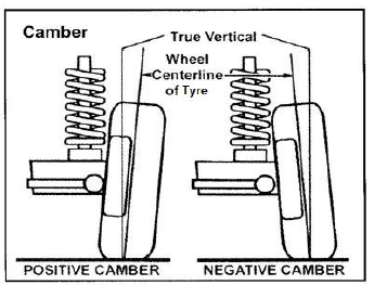
(4)
10.4 Advantages of positive camber:
- Easier steering ✓
- Better grip on cambered road ✓
- Worn out tyres are easy to identify ✓ (3)
10.5
10.5.1 Purpose of kingpin inclination:
It is designed to bring the front wheel back to the straight ahead position ✓after navigating a curve ✓ (2)
10.5.2 Purpose of Ackermann principle:
It is designed to enable a car to navigate a curve effectively ✓ without skidding ✓ (2)
10.6 Pre-checks on wheels:
- Check the tyre for bruises, cracks and damaged side walls. ✓
- Check the rim for damaged beads. ✓
- Check for foreign matter on the rim and tyres. ✓ (3)
10.7 Purpose of the catalytic converter:
It converts the pollutants in the exhaust gases of the engine into a non-toxic substance, making it environmentally friendly. ✓ (1)
10.8 Requirements for a catalytic converter to function properly:
- Unleaded petrol must be used. ✓
- Working temperature must not be less than 250 0C. ✓
- The ignition system must be accurately control. ✓
- The Lambda probe exhaust gas sensor must function correctly. ✓
- Persistent misfire damages the ceramic monolith. ✓
- Burnt engine oil also damages the monolith. ✓ (Any 3 x 1) (3)
10.9
10.9.1 Manifold absolute pressure (MAP) sensor and the air flow meters are used to measure the intake air volume ✓✓ (2)
10.9.2 Idle speed control (ISC)valve is controlled by ECU to regulates the idle speed ✓✓ (2)
10.9.3 Throttle position sensor (TPS) provides information about the position of the throttle valve to the ECU ✓✓ (2)
10.9.4 Mass air flow meter is used to measure the engine load conditions. ✓✓ (2)
[32]
TOTAL: 200