ELECTRICAL TECHNOLOGY GRADE 12 QUESTIONS - AMENDED SENIOR CERTIFICATE EXAMS PAST PAPERS AND MEMOS MAY/JUNE 2018
Share via Whatsapp Join our WhatsApp Group Join our Telegram GroupELECTRICAL TECHNOLOGY
GRADE 12
AMENDED SCE PAST PAPERS AND MEMOS
MAY/JUNE 2018
INSTRUCTIONS AND INFORMATION
- This question paper consists of SEVEN questions.
- Answer ALL the questions.
- Sketches and diagrams must be large, neat and fully labelled.
- Show ALL calculations and round off answers correctly to TWO decimal places.
- Number the answers correctly according to the numbering system used in this question paper.
- You may use a non-programmable calculator.
- Show the units for ALL answers of calculations.
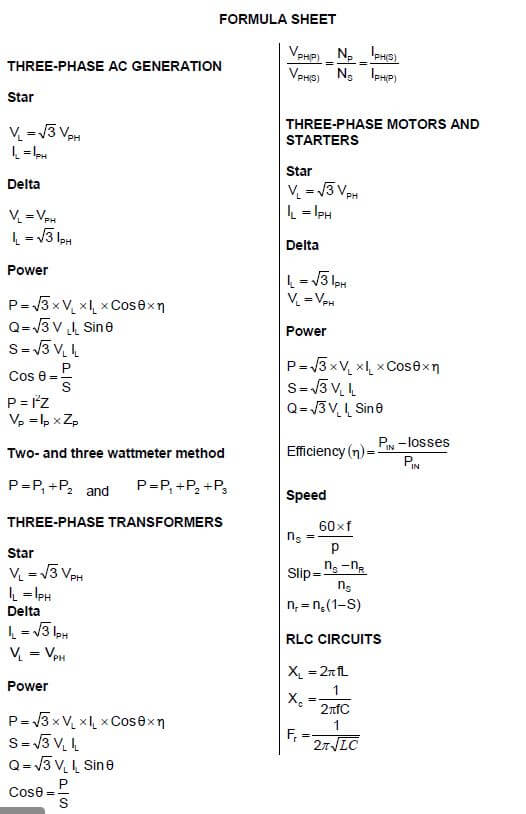
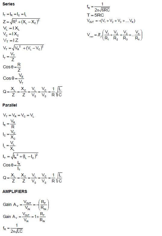
- A formula sheet is provided at the end of this question paper.
- Write neatly and legibly.
QUESTIONS
QUESTION 1: OCCUPATIONAL HEALTH AND SAFETY
1.1 Explain the importance of having the correct light intensity in an electrical technology workshop. (2)
1.2 With reference to the workshop, explain the term dangerous practices. (2)
1.3 State TWO actions that take priority in a medical emergency. (2)
1.4 Describe how HIV/Aids can affect productivity in the workplace. (2)
1.5 Explain why it is ethically correct to report a person who is working under the influence of strong medication that causes drowsiness. (2) [10]
QUESTION 2: THREE-PHASE AC GENERATION
2.1 State TWO disadvantages of single-phase power generation. (2)
2.2 Describe how an emf is induced in the coils of a three-phase AC system. (3)
2.3 A delta-connected alternator generates 220 V per phase. Each phase has an impedance of 16 Ω.
Given:
VPH = 220 V
ZPH = 16 Ω
Calculate the:
2.3.1 Current flowing in each phase (3)
2.3.2 Power dissipated per phase (3)
2.4 With reference to power factor correction, answer the questions that follow.
2.4.1 Name ONE method that can be employed to improve the power factor of a system. (1)
2.4.2 Give TWO reasons for improving the power factor of a system. (2)
2.5 The three-wattmeter method is used in a three-phase supply system to determine the power delivered to a three-phase, star-connected inductive load. The load has a power factor of 0,8 lagging. The readings on the wattmeters are 8 kW, 4 kW and - 460 W respectively. The supply voltage is 380 V.
Given:
P1 = 8 kW
P2 = 4 kW
P3 = - 460 W
p.f. = 0,8 lagging
VL = 380 V
Calculate the:
2.5.1 Total input power delivered to the load (3)
2.5.2 Current drawn by the load (3) [20]
QUESTION 3: THREE-PHASE TRANSFORMERS
3.1 With reference to the construction of transformers, answer the questions that follow.
3.1.1 Name TWO types of transformer construction. (2)
3.1.2 State why the iron core of transformers is laminated. (1)
3.2 Describe how an emf is induced in the secondary winding of a transformer. (3)
3.3 State TWO requirements that must be met before three single-phase transformers are connected to form a three-phase transformer. (2)
3.4 State the function of the oil in oil-filled transformers. (1)
3.5 A three-phase 300 kVA step-down transformer has a star-connected secondary with a phase voltage of 220 V. 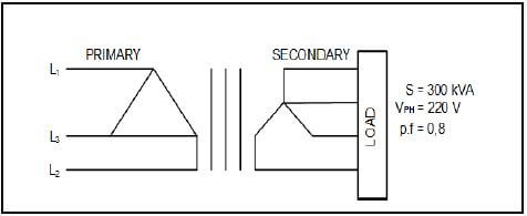
FIGURE 3.5: THREE-PHASE TRANSFORMER
Given:
S = 300 kVA
VPH = 220 V
p.f. = 0,8 lagging
Calculate the:
3.5.1 Secondary line voltage (3)
3.5.2 Maximum allowable secondary phase current (5)
3.5.3 Maximum output power at a power factor of 0,8 lagging (3) [20]
QUESTION 4: THREE-PHASE MOTORS AND STARTERS
4.1 With reference to the construction of motors, state the functions of the following parts of the motor:
4.1.1 Endplates (1)
4.1.2 The cooling fins (1)
4.1.3 The terminal box (1)
4.2 State THREE advantages of three-phase motors. (3)
4.3 A 12 pole, three-phase induction motor is connected across a 380 V, 50 Hz supply. The motor has a slip of 0,04.
Given:
VL = 380 V
Slip = 0,04
f = 50 Hz
∴p=2 pole pairs per phase
No. of poles =12 poles
Calculate the:
4.3.1 Synchronous speed of the motor (3)
4.3.2 Rotor speed of the motor (3)
4.4 A three-phase star-connected motor draws a current of 15 A when connected to a 380 V, 50 Hz supply. The motor has a power factor of 0,8 with an efficiency of 90%.
Given:
VL = 380 V
p.f = 0,8
IL = 15 A
ŋ = 90%
Answer the following questions.
4.4.1 Calculate the power of the motor at full load. (3)
4.4.2 Describe how the current drawn by the motor will be affected if the power factor of the motor is improved. (2)
4.5 The control circuit of a motor starter is shown in FIGURE 4.5 below. Study the circuit diagram and answer the questions that follow. 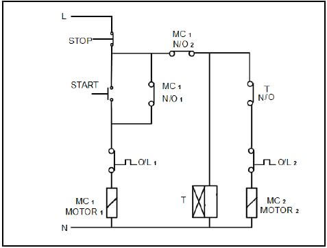
FIGURE 4.5: CONTROL CIRCUIT OF AN AUTOMATIC SEQUENCE STARTER
4.5.1 Explain why the normally open hold-in contact MC1 (N/O1) is connected in parallel with the start button. (4)
4.5.2 State, with a reason, whether the two motors are running. (3)
4.5.3 Explain the relevance of using two overload relays in the circuit. (3)
4.5.4 Describe how the starter achieves its function. (4)
4.5.5 State ONE application of the automatic sequence starter. (1)
4.6 List THREE mechanical inspections that must be carried out on an induction motor before putting it into service. (3)
4.7 FIGURE 4.7 below shows the terminal box of a three-phase induction motor. The resistance measured between the terminals is shown in the diagram. Explain, with reasons, if the motor is operational. 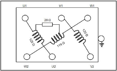
FIGURE 4.7: TERMINAL BOX (3)
4.8 State the function of the zero volt coil in a motor starter (2) [40]
QUESTION 5: RLC
5.1 State THREE factors that affect the impedance of an RLC circuit. (3)
5.2 Refer to the circuit in FIGURE 5.2 below and answer the questions that follow. 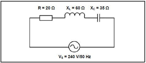
FIGURE 5.2: SERIES CIRCUIT
Given:
R = 20 Ω
XL = 60 Ω
XC = 35 Ω
VS = 240 V
f = 50 Hz
5.2.1 State whether the power factor of the circuit is leading or lagging. (1)
5.2.2 Calculate the power factor of the circuit. (5)
5.2.3 Explain what will happen to the Q factor of an RLC series circuit if R, L and C are doubled. (3)
5.3 An RLC series circuit is at resonance. Describe what will happen to the current in the circuit if the frequency is decreased below resonant frequency. (2)
5.4 Refer to the circuit diagram in FIGURE 5.4 below and answer the questions that follow. 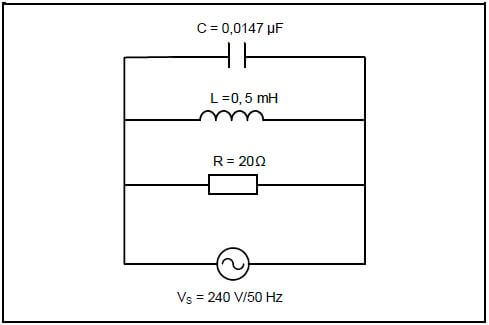
FIGURE 5.4
Given:
C = 0,0147 µF
L = 0,5 mH
R = 20 Ω
VS = 240 V
f = 50 Hz
Calculate the:
5.4.1 Frequency at which the circuit will resonate (3)
5.4.2 Current flowing through the resistor at resonance (3) [20]
QUESTION 6: LOGIC
6.1 Draw the symbol of EACH of the following, when using ladder logic with respect to programmable logic controllers (PLC):
6.1.1 An input device (1)
6.1.2 Relay or other device used as an output (1)
6.2 Name the logic system that was replaced by PLCs. (1)
6.3 Name ONE programming device used to program a PLC. (1)
6.4 Magnetic relays are still used to switch high-current devices on or off. Recommend ONE other device that could be used to switch high-current devices using PLCs. (1)
6.5 Explain the term program with respect to a PLC. (2)
6.6 Name TWO programming languages, other than ladder logic, used to program PLCs. (2)
6.7 Describe the functions of the following:
6.7.1 Timer function (2)
6.7.2 Marker (2)
6.8 Explain why a Boolean expression must be simplified before it is converted to a ladder program. (2)
6.9 Draw the logic gate diagram that will represent the following Boolean expression: ![]() (6)
(6)
6.10 Simplify the following expression using Boolean algebra: (Show ALL steps.) ![]() (6)
(6)
6.11 Simplify the Boolean expression below by using a four-variable Karnaugh map: ![]() (8)
(8)
6.12 Refer to the circuit in FIGURE 6.12 below and draw the ladder logic diagram that will execute the same function in a PLC system. 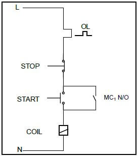
FIGURE 6.12: DIRECT-ON-LINE CONTROL CIRCUIT (5) [40]
QUESTION 7: AMPLIFIERS
7.1 Describe the following terms with reference to operational amplifiers:
7.1.1 Negative feedback (2)
7.1.2 Bandwidth (2)
7.2 FIGURE 7.2 below shows a non-inverting voltage comparator and the input voltage. 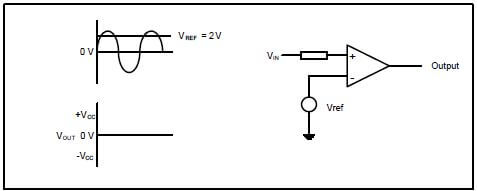
FIGURE 7.2
7.2.1 Redraw the input voltage and directly below it draw the output voltage wave form if the reference voltage is set at 2 V. (4)
7.2.2 State ONE application of the operational amplifier in FIGURE 7.2. (1)
7.3 Name the type of op amp circuit that uses positive feedback. (1)
7.4 Refer to FIGURE 7.4 below and draw the output of an ideal operational amplifier 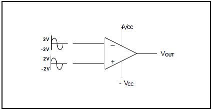
FIGURE 7.4: OPERATIONAL AMPLIFIER (2)
7.5 Refer to the circuit in FIGURE 7.5 below and answer the questions that follow. 2 kΩ 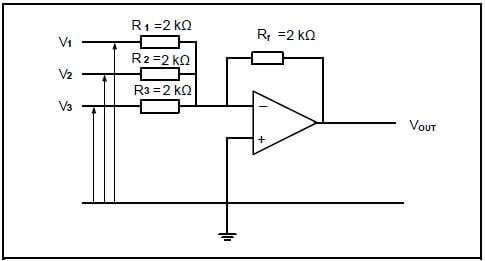
FIGURE 7.5: OP AMP CIRCUIT
7.5.1 Identify the circuit in FIGURE 7.5. (1)
7.5.2 State ONE application of the circuit. (1)
7.5.3 Calculate the amplitude of the output voltage if V1 has an amplitude of 0,5 V, V2 = 0,2 V and V3 = 0,2 V, all at the same frequency. (3)
7.6 Refer to FIGURE 7.6 below and answer the questions that follow.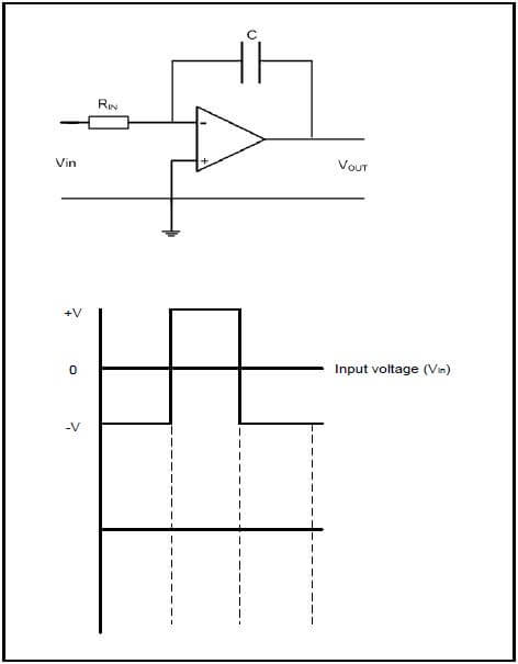
FIGURE 7.6: INTEGRATOR OP AMP CIRCUIT
7.6.1 Explain how the integrator circuit in FIGURE 7.6 can be changed to operate as an inverting operational amplifier. (2)
7.6.2 Draw and label the given input waveform and, in line directly below it, draw the output waveform. (4)
7.7 Refer to the circuit in FIGURE 7.7 below and answer the questions that follow. 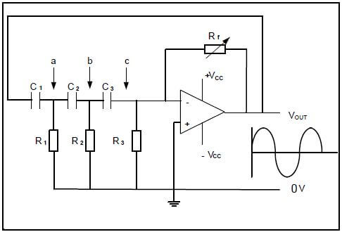
FIGURE 7.7: RC PHASE-SHIFT OSCILLATOR CIRCUIT
Given:
R1 = R2 = R3 = 8 kΩ
C1 = C2 = C3 = 275 x 10-12 F
7.7.1 State ONE application of the oscillator. (1)
7.7.2 Calculate the oscillating frequency of the oscillator. (3)
7.7.3 Redraw FIGURE 7.7.3 below in the ANSWER BOOK and draw the waveform represented at points a, b and c (in FIGURE 7.7 on page 15) with reference to the output. 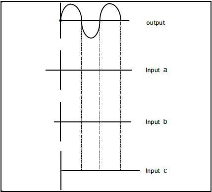
FIGURE 7.7.3 (3)
7.8 FIGURE 7.8 below shows the input to an inverting Schmitt trigger. Redraw the input wave and directly below it draw the output from the Schmitt trigger. 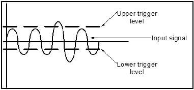
FIGURE 7.8 (4)
7.9 Calculate the resonating frequency of a Hartley oscillator consisting of two coils of 30 mH each and a capacitor of 0,35 µF.
Given:
L1 = 30 mH
L2 = 30 mH
C2 = 0,35 µF (3)
7.10 FIGURE 7.10 below shows a Colpitts oscillator circuit. Calculate the oscillation frequency of an operational Colpitts oscillator when an inductor of 2,6 H is connected in parallel with a series-connected combination of a 30 nF and 60 nF capacitor. 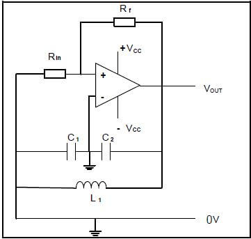
FIGURE 7.10: COLPITTS OSCILLATOR
Given:
L = 2,6 H
C1 = 30 nF
C2 = 60 nF (5)
7.11 With reference to FIGURE 7.11(a) below, draw the input wave form shown in FIGURE 7.11(b) and the output wave form directly below it. 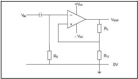
FIGURE 7.11(a) 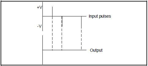
FIGURE 7.11(b) (5)
7.12 Answer the following questions with reference to a voltage follower.
7.12.1 State the application of the voltage follower when used between two circuits. (1)
7.12.2 Explain why the voltage follower is used between two circuits. (2) [50]
TOTAL: 200