CIVIL TECHNOLOGY GRADE 12 QUESTIONS - AMENDED SENIOR CERTIFICATE EXAMSPAST PAPERS AND MEMOS MAY/JUNE 2018
Share via Whatsapp Join our WhatsApp Group Join our Telegram GroupCIVIL TECHNOLOGY
GRADE 12
AMENDED SCE PAST PAPERS AND MEMOS
MAY/JUNE 2018
REQUIREMENTS:
- Drawing instruments
- A non-programmable calculator
- ANSWER BOOK
INSTRUCTIONS AND INFORMATION
- This question paper consists of SIX questions.
- Answer ALL the questions.
- Answer each question as a whole. Do NOT separate subsections of questions.
- Start the answer to EACH question on a NEW page.
- Do NOT write in the margins of the ANSWER BOOK.
- You may use sketches to illustrate your answers.
- Write ALL calculations and answers in the ANSWER BOOK or on the attached ANSWER SHEETS.
- Use the mark allocation as a guide to the length of your answers.
- Make drawings and sketches in pencil, fully dimensioned and neatly finished off with descriptive titles and notes to conform to the SANS/SABS Code of Practice for Building Drawings.
- For the purpose of this question paper, the size of a brick should be taken as 220 mm x 110 mm x 75 mm.
- Use your own discretion where dimensions and/or details have been omitted.
- Answer QUESTIONS 2.7, 3.5, 4.3, 5.2, 5.3, 6.1 and 6.2 on the attached ANSWER SHEETS using drawing instruments, where necessary.
- Write your CENTRE NUMBER and EXAMINATION NUMBER on every ANSWER SHEET and hand them in with your ANSWER BOOK, whether you have used them or not.
- Drawings in the question paper are NOT to scale due to electronic transfer.
- Google Images was used as the source for all photographs and pictures.
QUESTIONS
QUESTION 1: CONSTRUCTION, SAFETY AND MATERIALS
Start this question on a NEW page.
1.1 Study FIGURE 1.1 below that shows a worker drilling on a construction site and answer the questions that follow. 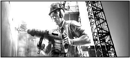
FIGURE 1.1
1.1.1 Describe the purpose of the hard hat. (1)
1.1.2 Explain how the worker can protect himself from the dust caused by the drill. (1)
1.1.3 Describe the consequences if safety equipment is not used by the worker whilst drilling. (1)
1.2 FIGURE 1.2 below shows safety equipment used for personal protection. 
FIGURE 1.2
1.2.1 Identify the safety equipment. (1)
1.2.2 Name ONE specific place/working area where this equipment will be used. (1)
1.3 FIGURE 1.3 below shows the line diagram of a roof truss. 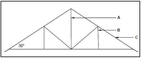
FIGURE 1.3
1.3.1 Identify the type of roof truss. (1)
1.3.2 Identify parts A to C of the roof truss. (3)
1.3.3 Motivate why the roof truss in FIGURE 1.3 cannot be covered with grass (thatch). (1)
1.3.4 Name ONE roof covering that can be used for the roof in FIGURE 1.3 if battens (38 mm x 38 mm) are used to keep the roof covering in place. (1)
1.4 Explain the difference between DPC (damp proof course) and a DPM (damp proof membrane) in terms of where it is used. (2)
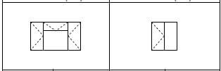
1.5 Differentiate between a standard clay brick and a queen closer by means of TWO freehand two-dimensional drawings in good proportion. Draw the view of the headers only. Label EACH drawing and write down the width and height of each brick. (5)
1.6 Corrosion of steel sections can be prevented by either painting or galvanising them. Recommend ONE of the methods and explain why you recommend it. (1)
1.7 Name any TWO preservatives that can be used to preserve timber. (1)
1.8 Draw a neat sketch of a tongue and groove board used for flooring. (3)
1.9 Describe the purpose of cement in concrete. (1)
1.10 Distinguish between mass concrete and reinforced concrete. (2)
1.11 During the casting of fresh concrete many air bubbles that cause voids are trapped in the concrete. Name TWO ways in which trapped air in concrete can be removed. (1)
1.12 Explain the difference between a slump test and a cube test in terms of the purpose of each test. (2)
1.13 Name the component used to close the gap/opening between two adjacent gypsum ceiling boards. (1) [30]
QUESTION 2: ADVANCED CONSTRUCTION AND EQUIPMENT
Start this question on a NEW page.
2.1 FIGURE 2.1 below is a sketch of a precast concrete pile driven into the ground. 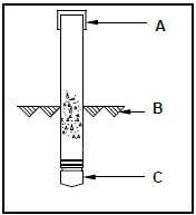
FIGURE 2.1
2.1.1 Name parts A and C. (2)
2.1.2 What does symbol B indicate? (1)
2.1.3 What equipment is used to drive this type of pile into the ground? (1)
2.1.4 Under what conditions will a pile foundation be used? (2)
2.2 Explain how you will use a transparent pipe level to transfer levels from one point to another. The pipe is already filled with water. (2)
2.3 You must lay tiles on a floor. Name any THREE tools that can be used to set out the floor for the tiles. (3)
2.4 FIGURE 2.4 below is a machine that is used in the building environment. 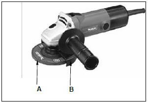
FIGURE 2.4
2.4.1 Identify the tool in FIGURE 2.4. (1)
2.4.2 Identify part A. (1)
2.4.3 Describe the function of part B. (1)
2.5 Arches are commonly used in the building industry.
2.5.1 Name the timber construction that has to be constructed to support the bricks of a semi-circular arch. (1)
2.5.2 Name the brick that is in the middle of the semi-circular arch. (1)
2.6 FIGURE 2.6 below shows a concrete beam with defects caused by forces acting on them. Name the types of forces that are responsible for the defects at A en B. 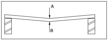
FIGURE 2.6 (2)
2.7 FIGURE 2.7 on the ANSWER SHEET shows an incomplete sectional view of a cavity wall.
Use ANSWER SHEET 2.7 to complete the cavity wall by drawing the following in good proportion:
- Six brick courses above the existing two courses (2)
- Mortar between brickwork (1)
- Symbol for concrete in the cavity between the walls (1)
- Symbol for concrete in the foundation (1)
- The symbol for back filling on one side only (1)
- The damp proof between the walls and the cavity (2)
- The weep hole (1)
- One wall tie (1)
2.8 A garage needs to be converted to a bachelor's flat. Due to limited time and the cost of labour, brick walls are not considered. Name a type of light-weight wall that can be used to divide the garage into rooms. (1)
2.9 Describe ONE disadvantage of the type of wall named in QUESTION 2.8. (1)
2.10 FIGURE 2.10 below shows an incomplete sectional view of a reinforced beam. 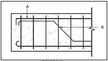
FIGURE 2.10
2.10.1 Identify A and B. (2)
2.10.2 Name ONE negative consequence if there is no reinforcement in concrete. (1)
2.10.3 State ONE function of stirrups. (1)
2.11 FIGURE 2.11 below shows formwork for a round column. 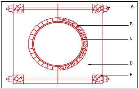
FIGURE 2.11
Identify A to E. (5)
2.12 Rearrange the stages below in the correct order to erect the rib and block floor. Write down only the letters (A–C) in the correct order in the ANSWER BOOK.
- Place reinforcing on top of hollow blocks.
- Pack all the hollow blocks between the ribs.
- Place ribs on supporting walls. (1) [40]
QUESTION 3: CIVIL SERVICES
Start this question on a NEW page.
3.1 Choose a description from COLUMN B that matches an item in COLUMN A. Write only the letter (A–H) next to the question numbers (3.1.1 to 3.1.6) in the ANSWER BOOK, e.g. 3.1.7 F.
COLUMN A | COLUMN B |
3.1.1 Pressure reducing valve |
|
3.2 Where would you install a water trap? (1)
3.3 Name ONE type of water trap that is used at a hand wash basin. (1)
3.4 Draw the following electrical symbols:
3.4.1 Socket outlet (2)
3.4.2 Two-way switch (2)
3.4.3 Light wall mounted (2)
3.5 On ANSWER SHEET 3.5 complete the drawing of a sectional view of a septic tank and show the following on your drawing:
- External walls with plaster and holes
- Inner wall with hole and plaster
- Inlet pipe with T-junction
- Outlet pipe with T-junction
- Liquid level
- Concrete cover with manholes (11)
3.6 In the absence of piped water from the municipality, name ONE other source of fresh water that is suitable for human consumption. (1)
3.7 Describe the main function of a storm-water system. (1)
3.8 Coal is the primary energy source used in South Africa to generate electricity. Name ONE other source from which electricity can be generated. (1)
3.9 Describe ONE advantage of a solar geyser. (1)
3.10 Describe ONE possible way in which a consumer could reduce electricity consumption in a home. (1) [30]
QUESTION 4: QUANTITIES, MATERIALS AND JOINING
Start this question on a NEW page.
4.1 Various options are given as possible answers to the following questions. Choose the answer and write only the letter (A–D) next to the question numbers (4.1.1 to 4.1.5) in the ANSWER BOOK, e.g. 4.1.6 C.
4.1.1 … are used to connect steel roof parts, steel columns and in situ timber trusses.
- Steel nails
- Bolts and nuts
- Dry-wall screws
- Cavity anchor (1)
4.1.2 A/An … is a type of nail used to attach ceiling boards to the brandering.
- wire nail
- cut nail
- clout nail
- oval wire nail (1)
4.1.3 … is used to join copper pipes.
- Brazing rod
- Welding rod
- Grease
- Solder (1)
4.1.4 … are used to join the members of a timber roof truss to one another.
- Gang nails/A connector plate
- Clout nails
- Rawl bolts
- Screws (1)
4.1.5 … can be used to join a roof truss to brickwork.
- Bolt and nut
- Sleeve anchor
- Hoop iron
- All the above-mentioned (1)
4.2 FIGURE 4.2 below shows the front view of a two-panel door. Study the drawing and complete the incomplete cutting list below. Write only the answer next to the question numbers (4.2.1 to 4.2.7) in the ANSWER BOOK. 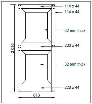
FIGURE 4.2 (7)
MEMBER | QUANTITY | UNIT | LENGTH | WIDTH | THICKNESS | MATERIAL |
Stile | 2 | mm | 4.2.1 | 114 | 44 | Saligna |
Top rail | 4.2.2 | mm | 813 | 114 | 4.2.3 | Saligna |
Lock rail | 1 | mm | 4.2.4 | 4.2.5 | 44 | Saligna |
Raised and fielded panel | 2 | mm | 768 | 612 | 4.2.6 | Saligna |
Bottom rail | 1 | mm | 813 | 4.2.7 | 44 | Saligna |
4.3 FIGURE 4.3 below shows the floor plan of a garage with a garage door, a side door and a window. 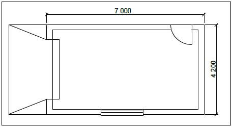
FIGURE 4.3
SPECIFICATIONS:
- The superstructure is a one-brick wall, 220 mm wide and 2 600 mm high.
- The side door opening is 2 100 mm high x 900 mm wide.
- The garage door is 2 400 mm wide x 2 100 mm high.
- The window opening is 1 500 mm wide x 450 mm high.
Use ANSWER SHEET 4.3 and calculate the total area of the walls for the superstructure that needs to be built after deducting all the openings. (18) [30]
QUESTION 5: APPLIED MECHANICS
Start this question on a NEW page.
5.1 FIGURE 5.1 shows a shaped lamina. All dimensions are in millimetres. Study the lamina and calculate the centroid of the lamina form A-A.
HINT: Use the formulae on the FORMULA SHEET. 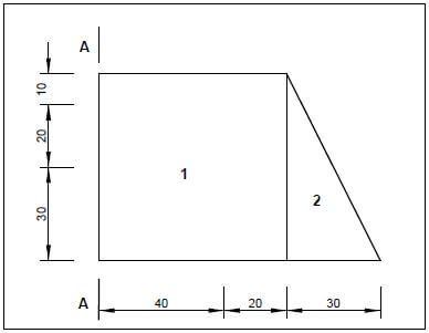
FIGURE 5.1 (9)
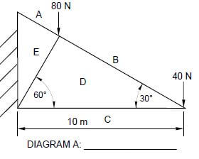
5.2 ANSWER SHEET 5.2 shows a diagram of a cantilever frame. Use ANSWER SHEET 5.2 to answer the following questions.
5.2.1 Name DIAGRAM A. (1)
5.2.2 On ANSWER SHEET 5.2, develop and draw a diagram to determine graphically the nature of the forces in each member (part) of the cantilever frame. Use scale 1 mm = 1 N. (6)
5.2.3 Use the information in the diagrams and complete the table on ANSWER SHEET 5.2. (3)
5.3 FIGURE 5.3 shows the space diagram of a beam with a span of 8 metres with two point loads and a uniformly distributed load. Study the diagram and answer the questions that follow. 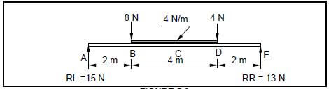
FIGURE 5.3
5.3.1 Convert the uniformly distributed load to a point load and write down the value of the converted point load. (1)
5.3.2 Determine the distance of the converted uniformly distributed load that is now a point load, from RR. (1)
5.3.3 Determine the distance of the 4 N point load, from RL. (1)
5.3.4 The value of the shear forces at A = 15 N, B = 7 N, D = -9 N, D1 = -13 N and E = 0 N. Use the available information and draw the shear force diagram on ANSWER SHEET 5.3. Use a scale of 2 mm = 1 N. (8) [30]
QUESTION 6: GRAPHICS AND COMMUNICATION
6.1 FIGURE 6.1 below illustrates a detailed sectional view of the foot of a king post roof truss. Study the drawing and complete the table on ANSWER SHEET 6.1. 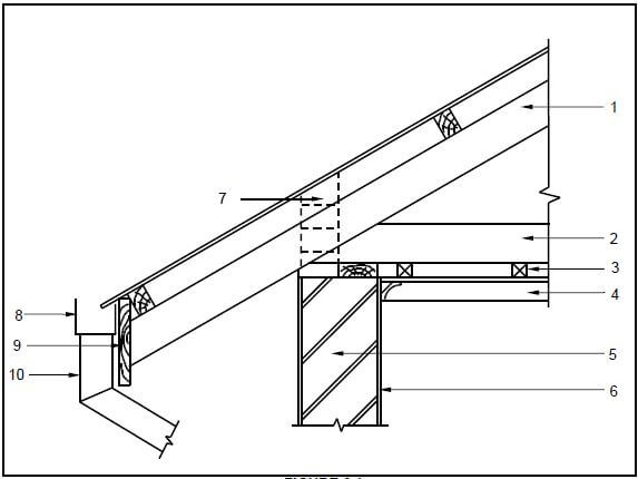
FIGURE 6.1
6.2 FIGURE 6.2 below shows the floor plan of a two-bedroom house. 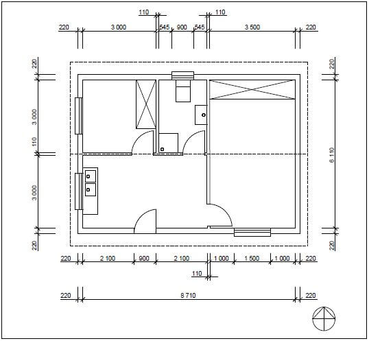
FIGURE 6.2
6.2.1 Study FIGURE 6.2 and develop and draw, on ANSWER SHEET 6.2, to scale 1 : 50, the SOUTH ELEVATION of the building. Use the specifications below.
(Use the assessment criteria on ANSWER SHEET 6.2 as a guideline for your drawing).
SPECIFICATIONS:
- The height between the natural ground level and the top level of the floor slab is 300 mm.
- The height between the floor slab and the underside of the wall plate is 2 600 mm.
- The roof is covered with galvanised roof sheeting with a 228 mm wide fascia board.
- Ridge capping is 100 mm high.
- Rainwater downpipes are 75 mm in diameter and 100 mm square gutters are used.
- One rainwater downpipe must be placed on each side the of the roof.
- The eaves overhang is 500 mm and the verge overhang is 300 mm.
- The door opening is 2 100 mm high and 900 mm wide.
- The door step is 150 mm high.
- The building has a gable roof with a pitch of 30°.
The following must also be shown on the drawing:
- The method used to determine the roof height
- Windows sills
WINDOW SCHEDULE | |||
Window 1(W1) | Window 2(W2) | ||
 | |||
Width | Height | Width | Height |
1 500 mm | 1 200 mm | 900 mm | 600 mm |
THREE marks will be allocated for the application of scale.
Start your drawing from corner A as indicated on ANSWER SHEET 6.2. (25) [40]
TOTAL: 200
CENTRE NUMBER: |
EXAMINATION NUMBER: |
ANSWER SHEET 2.7 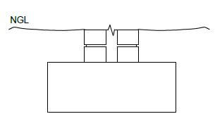
FIGURE 2.7
ASSESSMENT CRITERIA | MARK | CANDIDATE'S MARK |
Six brick courses above the two existing courses | 2 | |
Mortar between brickwork | 1 | |
Symbol for concrete in the cavity between the walls | 1 | |
Symbol for concrete in the foundation | 1 | |
The symbol for back filling on one side only | 1 | |
The damp-proof course between the walls and the cavity | 2 | |
The weep hole | 1 | |
One wall tie | 1 | |
TOTAL: | 10 |
CENTRE NUMBER: |
EXAMINATION NUMBER: |
ANSWER SHEET 3.5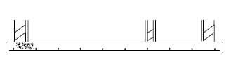
ASSESSMENT CRITERIA | MARK | CANDIDATE'S MARK |
External walls with plaster and holes | 3 | |
Inner wall with hole and plaster | 2 | |
Inlet pipe with T-junction | 2 | |
Outlet pipe with T-junction | 2 | |
Liquid level | 1 | |
Concrete cover with manholes | 1 | |
TOTAL: | 11 |
CENTRE NUMBER: |
EXAMINATION NUMBER: |
ANSWER SHEET 4.3
Complete your answers in the spaces indicated with ... and .... .
A | B | C | D |
Centre line: Superstructure | |||
2 / … = … | |||
2 / … = … | |||
Total = … | |||
Minus 4 / … = … | |||
= … | |||
1/ | … | Area of walls for superstructure: | |
… | … | ||
1/ | … | Area of side door: | |
… | … | ||
1/ | … | Area of garage door: | |
… | … | ||
1/ | … | Area of window: | |
… | … | ||
Total area of wall after deductions: | |||
= … … … … | |||
= … | |||
(18) |
CENTRE NUMBER: |
EXAMINATION NUMBER: |
ANSWER SHEET 5.2
 (1)
(1)
![]() (6)
(6)
DIAGRAM A IS NOT ACCORDING TO SCALE
MEMBER | NATURE |
AE | |
BD | |
CD | STRUT |
DE |
Tolerance of 1 N on both sides (3)
CENTRE NUMBER: |
EXAMINATION NUMBER: |
ANSWER SHEET 5.3 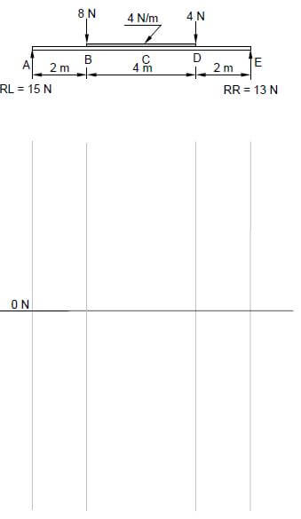
ASSESSMENT CRITERIA | MARKS | CANDIDATE'S MARK |
Correct shape of shear force diagram | 1 | |
Value of shear forces correctly measured | 5 | |
Horizontal lines indicated | 2 | |
TOTAL | 8 |
CENTRE NUMBER: |
EXAMINATION NUMBER: |
ANSWER SHEET 6.1
NO. | QUESTIONS | ANSWERS | MARKS |
1. | Identify the type of eave construction used in the drawing. | 1 | |
2. | State the minimum pitch (slope) of number 1, if galvanised roof sheeting is used. | 1 | |
3. | Identify number 2. | 1 | |
4. | State the standard dimension of number 3. | 1 | |
5. | State the purpose of number 4. | 1 | |
6. | Name the timber that is shown on top of the external wall marked number 5. | 1 | |
7. | Draw the drawing symbol for number 6 in the next column. | 2 | |
8. | Explain the purpose of number 7. | 1 | |
9. | Name ONE material that can be used for number 8. | 1 | |
10. | Identify number 9. | 1 | |
11. | Identify number 10. | 1 | |
12. | Draw a neat freehand line diagram of a fink or a W roof truss in the next column. | 3 | |
TOTAL: | 15 |
CENTRE NUMBER: | |||||||||||||
EXAMINATION NUMBER: |
ANSWER SHEET 6.2 A
| ASSESMENT CRITERIA | MARKS | CANDIDATES MARK |
External walls | 2 | |
NGL(correctly drawn) | 1 | |
FFL(correctly drawn) | 1 | |
Window | 1 | |
Window sill | 1 | |
Door opening | 1 | |
Step | 1 | |
Fascia board | 1 | |
Rainwater downpipe | 1 | |
Roof (correctly drawn) | 2 | |
Gutter | 1 | |
Ridge capping | 1 | |
Determining roof height | 4 | |
Any FOUR labels | 4 | |
Application of scale One or two incorrect = 3 Three or four incorrect = 2 More than five incorrect = 1 No measurement correct = 0 | 3 | |
TOTAL | 25 |
FORMULA SHEET
IMPORTANT ABBREVIATIONS
SYMBOL | DESCRIPTION | SYMBOL | DESCRIPTION | SYMBOL | DESCRIPTION |
c | Centroid | b | Breadth/Width | r | Radius |
ℓ | Length | s | Side | A | Area |
FORMULAE
| AREA OF | FORMULA (in words) | FORMULA (in symbols) | FORMULA FOR THE POSITION OF CENTROIDS | |
| X-axis | Y-axis | |||
| Square | side x side | s x s | s 2 | s 2 |
| Rectangle | length x breadth | ℓ x b | ℓ 2 | b 2 |
| Right-angled triangle | ½ x base x height | ½b x h | b 3 | h 3 |
| Equilateral triangle/ Isosceles triangle | ½ x base x height | ½b x h | b 2 | h 3 |
Position of centroid = (A1 x d) ± (A2 x d)
Total area
OR
Y = ΣAy
ΣA
OR
X = ΣAx
ΣA