ELECTRODYNAMICS: ELECTRICAL MACHINES - PHYSICAL SCIENCES PAPER 1 STUDY GUIDES AND NOTES
Share via Whatsapp Join our WhatsApp Group Join our Telegram GroupSummary
- Definitions
- Faraday’s law of electromagnetic induction
- Differences between motors and generators.
- Operations of motors and generators.
- Differences between direct current (DC) and alternating current (AC) in the cases of both motors and generators.
- The graphs of AC and DC.
- Right hand rule to determine the direction of the force on the conductor.
- The use of motors in everyday life.
- Calculations of the Root Mean Square.
DefinitionS AND LAWS YOU MUST REMEMBER
Magnetic flux (Φ) is the product of the strength of a magnetic field and the surface area the field cuts perpendicularly. It is measured in Wb (weber) units.
Electromagnetic induction is when a magnet moves relative to a conductor, and the magnet’s magnetic field is at right angles to the conductor, the maximum electric current is induced in the conductor.
Faraday’s Law of Electromagnetic Induction
- The induced emf in a conductor is directly proportional to the rate of change of the magnetic flux in the conductor.
- So ε ∝ ΔΦ
Δt - ε = – N ΔΦ where
Δt
N is the number of turns in the coil ε is emf in (V) volts
ΔΦ is change in magnetic flux in (Wb) weber Δt is change in time in (s) seconds - The negative sign shows that the emf creates a current and a magnetic field B that opposes the change in the magnetic flux Φ.
Electrodynamics is the study of the relationship between electricity, magnetism and mechanical phenomena.
8.1 Motors and Generators
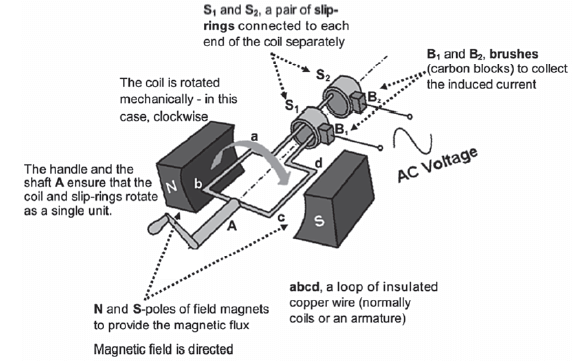
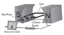
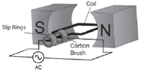
8.1.1. Alternating current generators
The principle of the AC generator
We know that, according to the phenomenon of electromagnetic induction:
- when an electric conductor moves in a magnetic field, there is a change in the magnetic flux which induces an emf that causes a current flow in the conductor;
- the magnetic field strength (B) that passes perpendicularly through a surface area A (in m2) is called the magnetic flux (Φ) and is measured in weber (Wb).

NB: Use the Right Hand Rule to determine the direction of the force on the charges (F) in the conductor of the generator – the conventional current direction (I) of the induced current.
The magnetic field (B) is in the North to South direction.
Remember it like so: First Finger is Field; SeCond finger is Current; ThuMb is Movement or Thrust.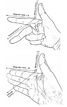
“Fleming’s left-hand rule is used for electric motors, while Fleming’s right-hand rule is used for electric generators.
Different hands need to be used for motors and generators because of the differences between cause and effect.”
(Wikipedia). So, if you’re trying to work out the direction of current in a generator, you need to use the Right Hand Rule, and, vice versa, if you’re trying to work out which way an electric motor will turn, you need to use the Left Hand Rule.
The fingers are the same; just the hand changes. Note also that an alternative hand positioning is to place all four fingers forwards (Field), and then the thumb indicates the thrust or motion, and a line perpendicular to the palm indicates the current.
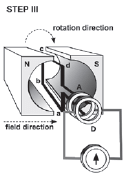
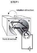
Step-by-step: The AC Generator
Suggestion: watch the video http://www.youtube.com/watch?v=wpCYiSFBQ0U (where 0 is zero)
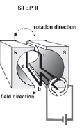
| Step I: Coil vertical: | Step II: Coil horizontal: |
|
|
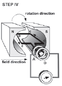
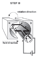
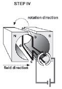
| Step III: Coil vertical: | Step IV: Coil horizontal: |
|
|
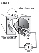
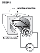
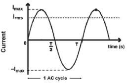
The alternating current (AC) cycle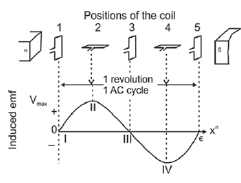
In AC (alternating current), the current changes voltage (and direction) every cycle; that is, every time the generator or dynamo turns over through one revolution (full cycle).
| When the coil is vertical (in coil positions 1, 3 and 5) | When the coil is horizontal (in coil positions 2 and 4) |
|
|
Increasing the induced emf and current
The induced emf (and therefore the amount of induced current) increases if:
- The conductor (wire) is rotated faster so that the rate at which the magnetic flux changes, increases;
- the magnetic field is stronger (use stronger magnets);
- there are more turns (loops) on the coil, so that the length of the conductor (wire) moving through the field is increased.
The direct current (DC) cycle
In DC (direct current), the current keeps the same voltage (and direction) in every cycle; that is, every time the generator or dynamo turns over through one revolution (full cycle).
| The direct current (DC) cycle | |
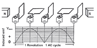 | |
| When the coil is vertical | When the coil is horizontal |
|
|
8.1.2 The difference between AC and DC generators
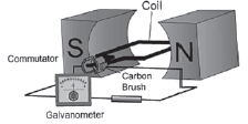
A direct current generator (dynamo) generates direct current instead of alternating current.
| Alternating current (AC) generator | Direct current (DC) generator |
 |  |
| Similarities between AC and DC generators | |
| |
| Differences between AC and DC generators | |
AC generator
| DC generator
|
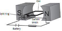
8.1.3 Electric motors
Parts of the direct current (DC) motor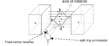
Use Fleming’s Right Hand Rule to determine the direction of the force on the conductor –the direction in which the coil turns. Remember: the current is in the direction of the middle finger or palm, whereas the magnetic field is in the direction of the fingers (or index finger), and the thrust (motion) is in the direction of the thumb.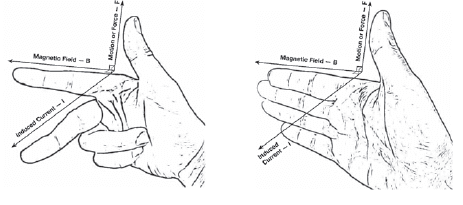
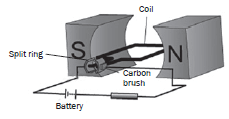
8.1.4 The working of a simple DC-motor
| Step 1: Coil horizontal at 0° | Step 2: Coil vertical at 90° |
|
|
| Step 3: Coil horizontal at 180° | Step 4: Coil vertical at 270° |
|
|
Increasing the speed at which the DC motor rotates (turns)
The coil will turn faster if:
- the current in the coil increases;
- the number of turns on the coil increases;
- the strength of the magnetic field increases.
8.1.5 The differences between AC and DC motors
| Alternating current (AC) motor | Direct current (DC) motor |
|
|
8.1.6 Differences between a motor and a generator
An electric motor and an electric generator are basically the same device.
The primary difference is in the case of a motor, electricity is used to turn it, whereas in the case of a generator, turning it mechanically generates electricity.
| Direct Current (DC) Motors | Direct Current (DC) Generators |
|
|
 Connected to a battery. The battery is a source of electric energy.
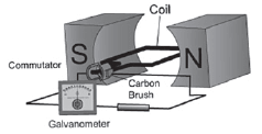
8.1.7 Electrical motors in everyday life
In practice, motors turn evenly at a high speed. The coil in a motor consists of a soft iron core, surrounded by coils. This coil forms the armature. Most armatures have many coils, which are placed at different angles. Each coil in the armature has its own commutator. This results in a bigger turning effect which makes the motor turn evenly. A very important example of an electric motor is the starter motor of a car, which turns the car engine over in order to start it. The purpose of the car battery is to power the starter motor (and other things like lights). When the car is running, the petrol motor turns a generator over which then recharges the battery.
Some motors, e.g. an electric drill, can also use alternating current because they contain electromagnets and not permanent magnets. As the alternating current flows in the coil, the magnetic field changes direction.
Thus the motor continues to turn in the same direction.
8.2 Alternating Current Circuits
Frequency: The frequency (f) of an alternating current supply is the number of complete cycles per second and is measured in hertz (Hz).
In South Africa electricity is supplied by Eskom power stations and has a frequency of 50 Hz.
Period: The period (T) of an alternating supply is the time taken to complete one cycle. If the frequency of the AC current is 50 Hz, T = 1 = 1 = 0,02 s
f 50
8.2.1 Voltage and current in an AC circuit
| emf induced by an AC generator | Current induced by an AC generator |
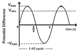 |  |
V varies in cycles
Voltage changes polarity twice in one AC cycle | I varies in cycles
Current changes direction twice in one AC cycle |
Definition
Root mean squared voltage
The root mean squared voltage (Vrms) is the equivalent DC voltage value that produces the same heating effect or power as the changing AC.
Vrms = Vmax Irms = Imax
√2 √2
The root mean squared current (Irms) is the effective current value of alternating current.
- Root mean square (rms) values are the AC equivalent of DC emf.
- If a DC circuit has an emf of 100 V and an AC circuit has a Vrms of 100 V, the circuits would use the same amount of power.
8.2.2 Electric power in an AC circuit
Definition
Electrical power (P) is the rate at which energy is transferred or transformed from one type to another.
Summary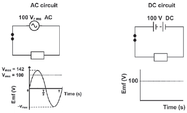
Vrms = Vmax = 100V
√2
V = 100
R = Vrms ∴ Vrms = IrmsR
Irms
R = V ∴ V = IR
I
Pavg = VrmsIrms = I2rmsR = Rrms2
R
Pavg : average power watt (W)
Vrms : rms potential difference volt (V)
Irms : rms current ampere (A)
R : resistance ohm (Ω)
Remember: 1 megavolt = 1 × 10⁶ volt
1 MV = 1 × 10⁶ V
8.2.3 Advantages of alternating current
- The most important advantage of AC is the fact that the potential difference can be changed by using transformers.
- Transformers can only function with alternating current.

- The power in a transformer remains constant and P = VI ∴ V ∝1/I
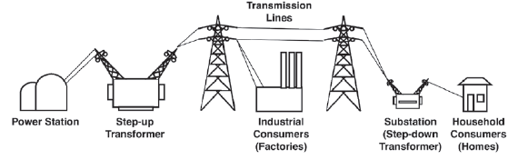
- At power stations step-up transformers are used to increase (step-up) the voltage which decreases the current.
- The voltage is increased to between 130 and 750 MV
- This allows electrical energy to be transmitted in electric cables over long distances while the current is low.
- The loss in energy due to the heating effect of the cables is low when the current (Ι) is small: W = I2Rt ∴ Wtransformed to heat ∝ I2
- Conducting cables are thick to help decrease the energy lost as heat during transmission.
- Factories need high voltage (± 10 kV).
- In towns step-down transformers are used to decrease (step-down) the voltage to ± 220 V. You can see these at the side of the road in most suburbs; they are painted dark green.
Activity 1
A simplified sketch of a generator is shown below.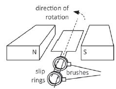
- Is the output voltage AC or DC? Give a reason for your answer. (2)
- What type of energy conversion takes place in the above generator? (2)
- State TWO effects on the output voltage if the coil is made to turn faster. (2)
- What is the position of the coil relative to the magnetic field when the output voltage is a maximum? (1)
[7]
Solutions
|
Activity 2
Lights in most households are connected in parallel, as shown in the simplified circuit below. Two light bulbs rated at 100 W; 220 V and 60 W; 220 V respectively are connected to an AC source of rms value 220 V. The fuse in the circuit can allow a maximum current of 10 A.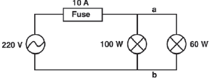
- Calculate the peak voltage of the source. (3)
- Calculate the resistance of the 100 W light bulb when operating at optimal conditions. (3)
- An electric iron, with a power rating of 2 200 W, is now connected across points a and b. Explain, with the aid of a calculation, why this is not advisable. (5)
[11]
Solutions
|
Activity 3
The essential components of a simplified DC motor are shown in the diagram below.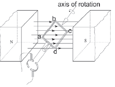
When the motor is functioning, the coil rotates in a clockwise direction as shown.
- Write down the function of each of the following components:
- Split-ring commutator (1)
- Brushes (1)
- What is the direction of the conventional current in the part of the coil labeled AB? Write down only FROM A TO B or FROM B TO A. (1)
- Will the coil experience a maximum or minimum turning effect (torque) if the coil is in the position as shown in the diagram above? (1)
- State ONE way in which this turning effect (torque) can be increased. (1)
- Alternating current (AC) is used for the long-distance transmission of electricity.
Give a reason why AC is preferred over DC for long-distance transmission of electricity. (2) - An electrical appliance with a power rating of 2 000 W is connected to a 230 V rms household mains supply.
Calculate the:- Peak (maximum) voltage (3)
- rms current passing through the appliance (3)
[13]
Solutions
|
Activity 4
Electric motors are important components of many modern electrical appliances. AC motors are used in washing machines and vacuum cleaners, and DC motors are used in toys and some tools.
- What energy conversion takes place in electric motors? (2)
- What is the essential difference in the design between DC motors and AC motors? (4)
- List THREE ways in which the efficiency of the motor can be improved. (3)
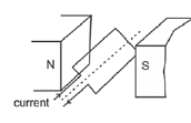
- Consider the diagram. The conventional current direction is indicated by the arrows.
- In which direction (clockwise or anti-clockwise) will the coiled armature rotate if the switch is closed? (1)
- Why does the armature continue moving in the same direction once it has reached the vertical position? (2)
[12]
Solutions
|
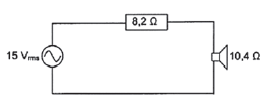
Activity 5
In the circuit the AC source delivers alternating voltages at audio frequency to the speaker.
- What is the peak voltage that the source can deliver? (3)
- Calculate the average power delivered to the speaker. (7)
[10]
Solutions
|